Do you have a question about the Miller Syncrowave 180 SD and is the answer not in the manual?
Explains hazard symbols used in the manual.
Details electric shock, fumes, gases, and other hazards related to arc welding.
Explains symbols for installation, operation, and maintenance hazards.
Lists relevant safety standards and codes.
Discusses electromagnetic fields and their effects, with reduction procedures.
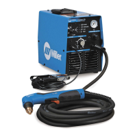
Lists the components included with the welding unit.
Guidelines for choosing a suitable location for the unit, considering airflow and movement.
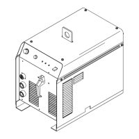
Provides physical dimensions and weight of the welding unit.
Details electrical and performance specifications for different welding modes.
Illustrates the duty cycle of the unit based on amperage and time.
Shows voltage and amperage output capabilities for AC and DC modes.
Explains weld output terminals and guides for selecting appropriate cable sizes.
Details the function and pinout of the remote 14 receptacle.
Provides instructions for connecting shielding gas to the unit.
Provides guidance on electrical service requirements for the unit.
Step-by-step instructions for connecting the input power.
Overview and explanation of the unit's front panel controls.
Demonstrates using the front panel for amperage adjustment in Stick welding.
Explains using remote controls for amperage adjustment in TIG welding.
Illustrates typical connection setups for TIG welding.
Illustrates typical connection setups for Stick welding.
A guide for selecting welding processes and output based on material type and thickness.
Outlines regular maintenance tasks and schedules for the unit.
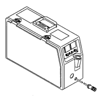
Instructions for adjusting spark gaps within the unit.
Provides solutions for common problems and issues encountered with the unit.
Explains how High Frequency is used in different welding processes.
Identifies sources of HF radiation due to improper installation.
Provides guidelines for correct installation to minimize HF interference.
Guide to selecting the correct tungsten electrode based on amperage and polarity.
Safety precautions and information when handling tungsten electrodes.
Instructions for preparing tungsten electrodes for DCEN welding.
Guidance on proper torch positioning for effective TIG welding.
Demonstrates correct torch movement techniques during TIG welding.
Shows how to position the torch tungsten for different weld joint types.
Step-by-step instructions for performing Stick welding.
A chart for selecting electrodes and amperage for SMAW welding.
Demonstrates the scratch start technique for striking an arc.
Demonstrates the tapping technique for striking an arc.
Guidance on correct positioning of the electrode holder for different weld types.
Illustrates common issues leading to poor weld bead quality.
Illustrates characteristics of a good weld bead.
Explains factors influencing weld bead shape like angle, arc length, and speed.
Demonstrates electrode movement techniques for stringer and weave beads.
Details different types of butt joints and their preparation.
Explains welding techniques for lap joints.
Explains welding techniques for tee joints.
Describes how to perform a weld test to check for quality.
Identifies causes and corrective actions for porosity in welds.
Identifies causes and corrective actions for excessive spatter.
Identifies causes and corrective actions for incomplete fusion in welds.
Identifies causes and corrective actions for lack of penetration in welds.
Identifies causes and corrective actions for excessive penetration in welds.
Identifies causes and corrective actions for burn-through in welds.
Identifies causes and corrective actions for waviness of weld beads.
Identifies causes and corrective actions for weld distortion.
Lists part numbers and descriptions for the main assembly of the unit.
Lists part numbers and descriptions for front panel components.
Details the terms, conditions, and periods of the limited warranty.
Lists items and conditions not covered by the Miller warranty.
A section to record purchase details and serial numbers for personal records.
Information on contacting distributors and service agencies for support.
| Welding Amperage Range | 10 - 180 A |
|---|---|
| Max. Open-Circuit Voltage | 80 V |
| Processes | TIG (GTAW), Stick (SMAW) |
| Input Power | 230V, 1-Phase, 50/60 Hz |
| Rated Output | 30% Duty Cycle |