OM-251981 Page 8
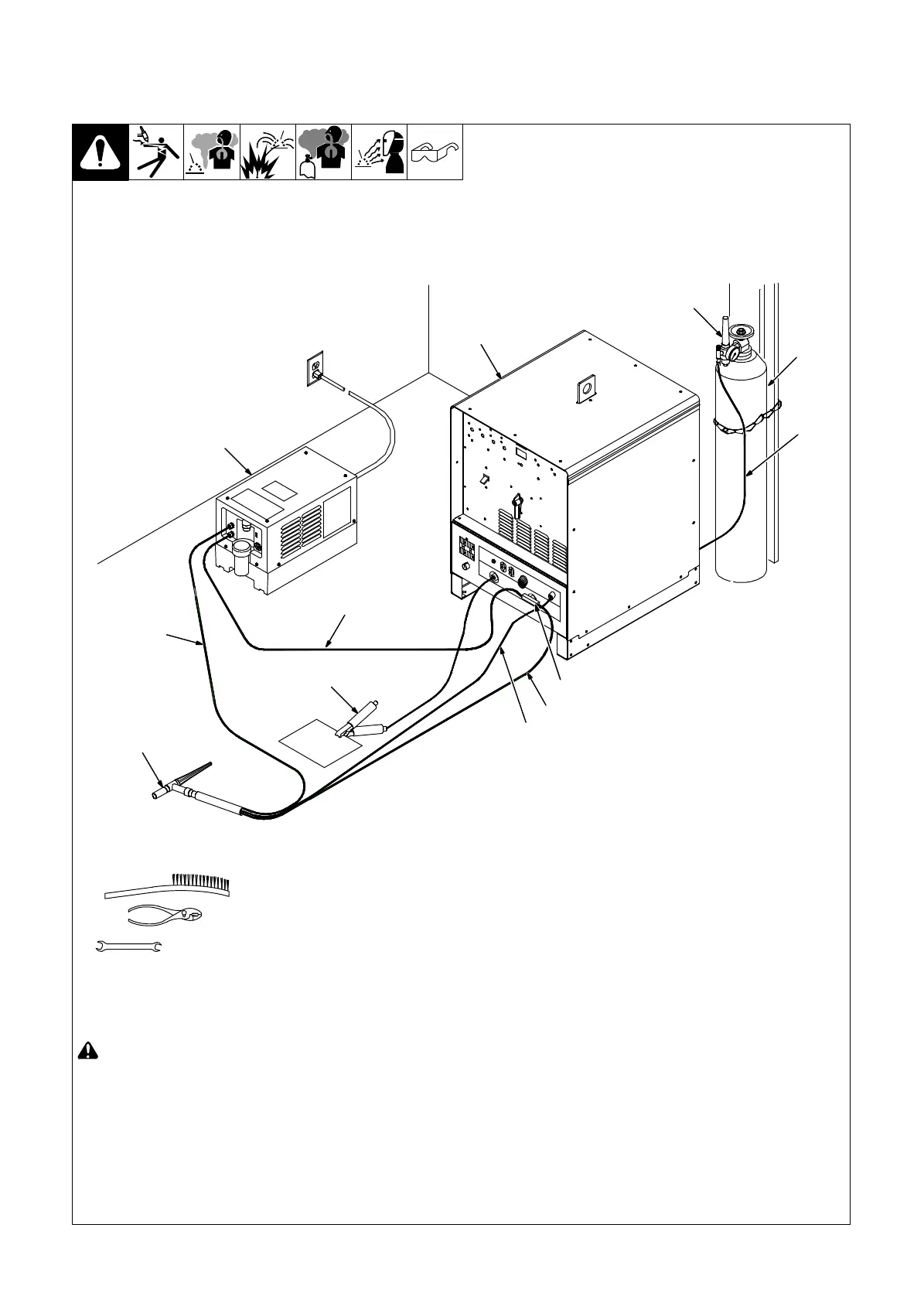
4-7. Connecting Torch
A. Connecting Water-Cooled Torch When Using A Freestanding Coolant System
! Turn Off welding power source and
cooling system power before in-
stalling torch.
. If applicable, install high-frequency
unit.
1 Welding Power Source
2 Regulator/Flowmeter
3 Gas Cylinder
4 Gas Hose (Customer Supplied)
Obtain correct length with 5/8-18 right-hand
fittings.
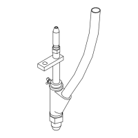
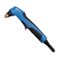
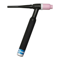
5 Torch
6 Power Cable Adapter
7 Coolant Hose (Customer Supplied)
Obtain correct length with 5/8-18 left-hand
fittings.
8 Coolant-Out Of Torch/Power Cable
(Red)
Connect coolant-out of torch/power cable
to power cable adapter, and connect adapt-
er to weld output terminal.
9 Torch Gas Hose
10 Coolant-Into Torch Hose (Blue)
11 Cooling System
12 Work Clamp
Connect work clamp to a clean, paint-free
location on workpiece, close to the weld.
Use wire brush or sandpaper to clean weld
joint area.
802560
Tools Needed:
5/8, 7/8, 1-1/8 in.
5
11
1
7
2
3
4
6
9
10
8
12
 Loading...