MPS Doc: M359_USER_MANUAL REV G January 17, 2010 Page 11 of 30
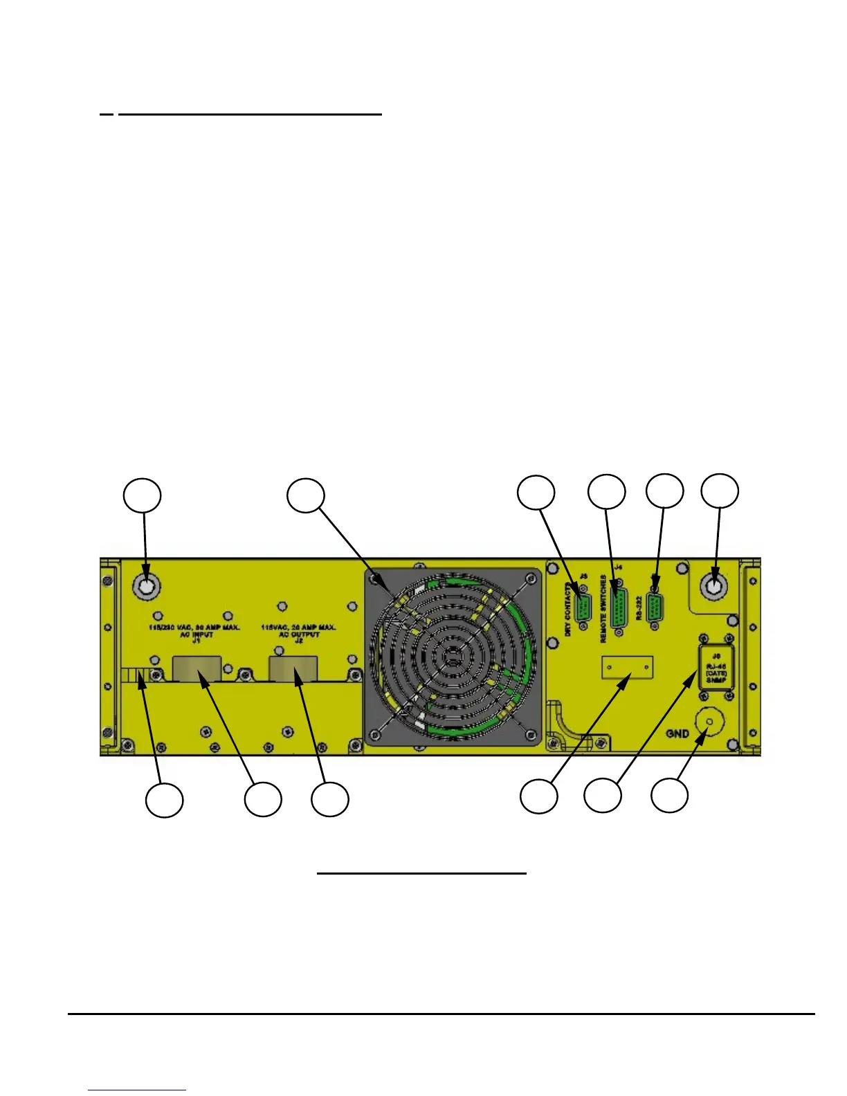
4. Rear Panel Description (Figure 5)
30. Left side Bushing (mating pins are supplied with the unit).
31. Cooling fan (air outlet).
32. Dry Contacts Connector J3 (see Paragraph 7.2 for pin-out description).
33. Remote ON/OFF connector J4 (see Paragraph 7.4 for pin-out description).
34. RS-232 Connector J5 (see Paragraph 7.3 for pin-out description).
35. Right side Bushing (mating pins are supplied with the unit).
36. Right-side GND Connection (threaded hole, .190, UNF-32, 1.5D(min) deep)
37. RJ-45 (CAT-5), Ethernet SNMP Port.
38. Mounting Provisions (4-40 threaded holes) for Ethernet Cable Support (not
provided).
39. J2 Output Power Connector (see Figure 2 for pin-out).
40. J1 Input Power Connector (see Figure 2 for pin-out).
41. Left-side GND Connection (threaded hole, .190, UNF-32, 1.5D(min) deep).
7$)<1#