MPS Doc: M359_USER_MANUAL REV G January 17, 2010 Page 9 of 30
3. Front Panel Description
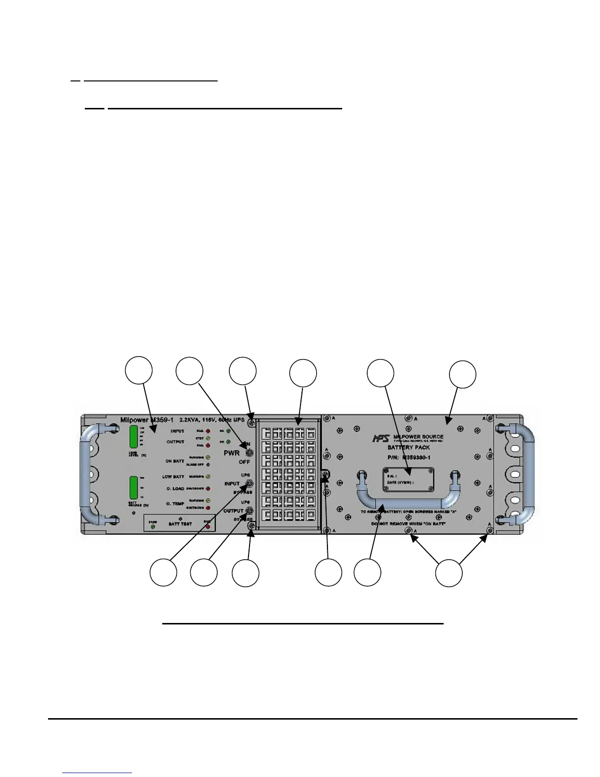
3.1. Front Panel: Main Components (Figure 3)
1. Visual Indicators and Controls (for detailed view see Figure 4)
2. Power On/Off Switch.
3. Air filter captive screw.
4. Removable air filter (Air Inlet).
5. Serial Number and Date Code of Battery Pack.
6. Plug-in, hot-swap Battery Pack.
7. Input UPS/By-Pass Select switch.
8. Output UPS/By-Pass Select switch.
9. Air filter captive screw.
10. Air filter captive screw.
11. Battery Pack handle.
12. Battery Pack mounting screws (total of 10, marked “A”).
7$)71#'$,!"