MPS Doc: M359_USER_MANUAL REV G January 17, 2010 Page 25 of 30
7.3. RS-232 Serial Interface
The RS-232 serial communication interface is available through connector J5 (34), a D-Type
9S connector, located on the back panel of the UPS. This port is a DTE.
;-"$#91+)$$##'$5
<88,#$"$$)!/1
(#0*
The RS-232 interface allows control and monitoring of the UPS by a host computer through
the serial RS-232 communication link. For further information about this feature refer to the
Software Interface Manual (available at www.milpower.com). The Table below shows the
RS-232 pin assignment. On the I/O column, “Input” and “Output” entries designate input and
output pins of the UPS.
7.4.
Remote Control Interface (Remote Switch)
$$""2$!$)"#))$:@'2$
B!"%#$*!#$$'!5$
*
The Remote Control Interface J4 (Fig 10, on next page) provides a means for turning the
UPS ON and OFF and selecting between the UPS Mode and the By-Pass Mode from a
remote panel’s switches. The Pin assignment of J4 is shown on the next page.
Pins 3, 4 and 5 are connected in parallel and serve as a Common Signals Return.
When Pin 8 (the remote PWR ON/OFF pin) is connected to the Common Signals Return, the
M359 is enabled. Opening Pin 8 will disable the M359 (opening all internal relays and
removing power from the Output) regardless of any other control or switch.
When Pin 6 (the remote UPS Select Pin) is connected to the Common Signals Return (and
Pin 7 is open, the UPS Mode will be enabled.
When Pin 7 (the remote By-Pass Select Pin) is connected to the Common Signals Return
and Pin 6 is open, the UPS will be forced into the By-Pass Mode (providing that Pin 8 is also
connected to the Common and the front panel PWR ON/OFF switch is in the On Position.)
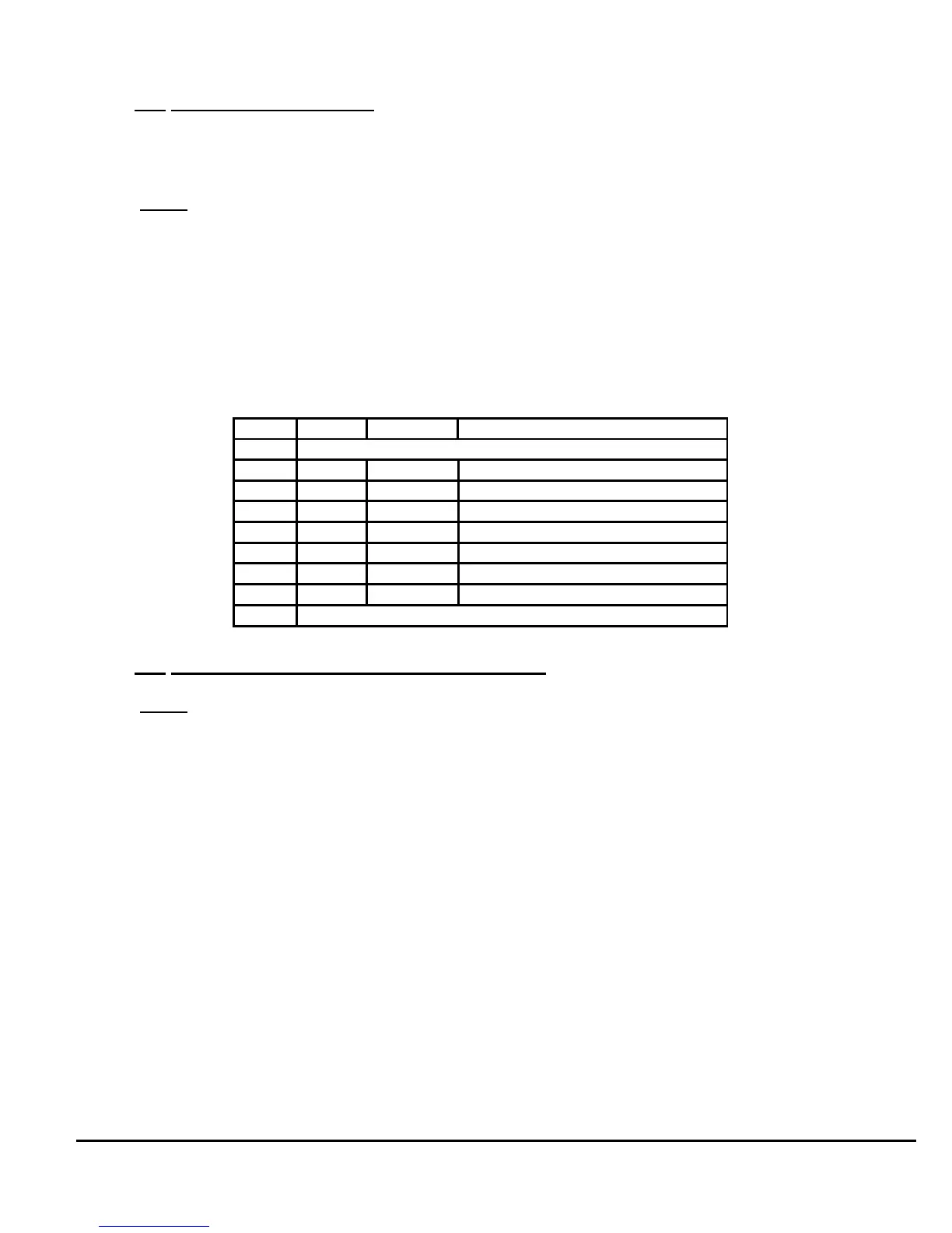
Connector J5 RS-232 Pin Assignment
Pin I/O Symbol Description
1 Internally shorted to J3 pin 5. (not used by RS232 link)
2 Input RXD Receive Data
3 Output TXD Transmit Data
4 Output DTR Data Terminal Ready
5 --------- SG Signal Ground
6 Input DSR Data Set Ready
7 Output RTS Request To Send
8 Input CTS Clear To Send
9 Internally shorted to J3 pin 9. (not used by RS232 link)