4
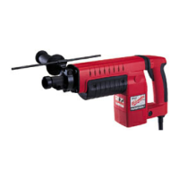
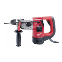
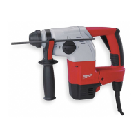
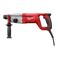
FUNCTIONAL DESCRIPTION
3
1
7
2
6
9
10
4
5
1. Side handle
2. Bit holder
3. Bit release collar
4. Side handle knob
5. Mode selector knob
8
6. Trigger
7. Trigger handle
8. Speed adjustment knob
9. Chisel lock
10.Service indicator
ASSEMBLY
To reduce the risk of injury, always
unplug tool before changing or
removing accessories. Only use accessories
specically recommended for this tool. Others
may be hazardous.
Always use a side handle when using this tool.
Always brace or hold securely.
Adjusting the Side Handle Position
1. Loosen the side handle by unscrewing the side
handle kbob until the side handle rotates freely.
2. Rotate the side handle to the desired position.
3. Tighten the side handle knob securely.
The grounding prong in the plug is connected through
the green wire inside the cord to the grounding
system in the tool. The green wire in the cord must
be the only wire connected to the tool's grounding
system and must never be attached to an electrically
“live” terminal.
Your tool must be plugged into an appro-
Fig. A
priate outlet, properly installed and
grounded in accordance with all codes
and ordinances. The plug and outlet
should look like those in Figure A.
Double Insulated Tools (Two-Prong Plugs)
Tools marked “Double Insulated” do not require
grounding. They have a special double insulation
system which satises OSHA requirements and
complies with the applicable standards
Fig. B
Fig. C
of Underwriters Laboratories, Inc., the
Canadian Standard Association and
the National Electrical Code. Double
Insulated tools may be used in either
of the 120 volt outlets shown in Figures
B and C.
SPECIFICATIONS
Cat. No. ..................................................... 5546-21
Volts .............................................................120 AC
Amps ...................................................................15
RPM ........................................................... 210-385
BPM ....................................................... 1600-2900
Type .........................................................SDS-Max
Twist bit..........................................................1-3/4"
Core bit ................................................................ 6"
Tunnel bit ....................................................... 2-1/2"
SYMBOLOGY
Volts
Alternating Current
Amps
No Load Revolutions per Minute (RPM)
BPM
Blows per Minute (BPM)
Anti-Vibration System
Read Operator's Manual
UL Listing for Canada and U.S.
Approval Mark for Mexico