Do you have a question about the Minco 820B and is the answer not in the manual?
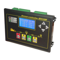
Overview of the panel's display, keys, and indicator lights.
Functions of menu keys and main operation buttons (RUN, AUTO, RESET).
Details the information displayed on the LCD screen during normal operation.
Function of the TEST key for manual generator testing.
Meaning of FAILURE, ALARM, and REMOTE START indicator lights.
Specifics on relay output ports and switch input ports for control signals.
Guidance on accessing and modifying controller parameters.
Real-time display of controller input and output port states.
Viewing shutdown records and setting the controller's date and time.
Configuring alarm thresholds and adjusting measured values.
Steps for authenticating with the controller's password.
Trip speed, CT ratio, password, address, and crank limit configuration.
Settings for gear tooth, opt.2, speed, load, coolant, oil pressure, oil temp, battery, phase, display, language, LCD.
Delays for cool stop, genset start, cranking time, crank interval, and bypass time.
Delays for ETS fuel, pre-fuel, idle start, and idle stop operations.
Delays for ACC, oil pressure, coolant temp, over speed, oil temp, loss speed, battery, transform, current, voltage, frequency, Dec. time, warm up.
Troubleshooting steps when manual start fails to engage the motor.
Troubleshooting for auto start failures and wheel tooth fighting.
Steps to resolve inaccurate current display and general fault handling.
Diagrams for MPU, speed sensor, remote start, voltage, current, battery, AVR, GEN connections.
Diagrams for governor, speed sensor, supply, battery, AVR, GEN connections.
Overview of front panel indicator lights and operation buttons.
Identification of ports and connections on the controller's back panel.
| Model | 820B |
|---|---|
| Type | Temperature Controller |
| Number of Inputs | 1 |
| Output Type | Relay, SSR |
| Communication Protocol | RS-485 Modbus RTU |
| Control Mode | PID, On/Off |
| Input Type | Thermocouple, RTD |
| Display | Dual LED display |
| Input Voltage | 100-240V AC, 50/60Hz |
| Power Supply | 100-240V AC, 50/60Hz |