3.2.6.3 Assembly and Disassembly of the Enclosure Assembly
The enclosure assembly is fixed by 11 screws which are connected to the base plate.
Of the 11 screws, 3 are located at the back of the system and the remaining which
can be dismounted directly are located under the enclosure. When assembling and
disassembling the enclosure, please pay attention to the following:
1 If the system is configured with flow cell, before opening the enclosure, move the
flow cell out of the installing location and place it in the hole for holding flow cell
temporarily. Otherwise, the tubing connection will be dragged off.
2 When opening the enclosure, do not drag the cable with excessive force.
3 Place the enclosure in a stable location to make it stand vertically. If the
enclosure falls down, some cables, especially the touchscreen board cable,
aspirate button cable, might be dragged.
When installing the LCD/touchscreen module, pay attention to the following as shown
in figure 3-14.
1 When installing LCD cable, the blue face (untouchable face) of the FPC should
face outward;
2 When installing the LCD data cable of LCD&touchscreen board, the metal face
of the FPC cable (touchable face) should face outward;
3 When installing the touchscreen data cable of LCD&touchscreen board, the
metal face of the FPC cable (touchable face) should face outward;
4 When installing the supporting plate of the touchscreen, tighten the four screws
gradually one by one to avoid uneven force on the screen and excessive
tightening force on the screw which will result in false reaction of the
touchscreen.
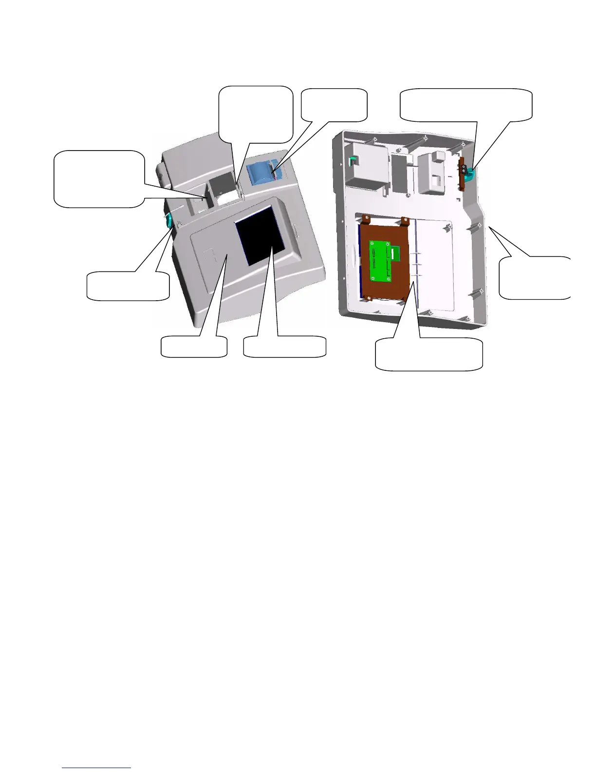
Enclosure Touchscreen
Aspirate button
Recorder
Touch screen
supporting board
Aspirate button movement
switch
Cover of
lamp
replacement
window
Enclosure
fixing screw
hole
Hole for holding
flow cell t
temporarily