4.5.6 Driver of the Step Motor
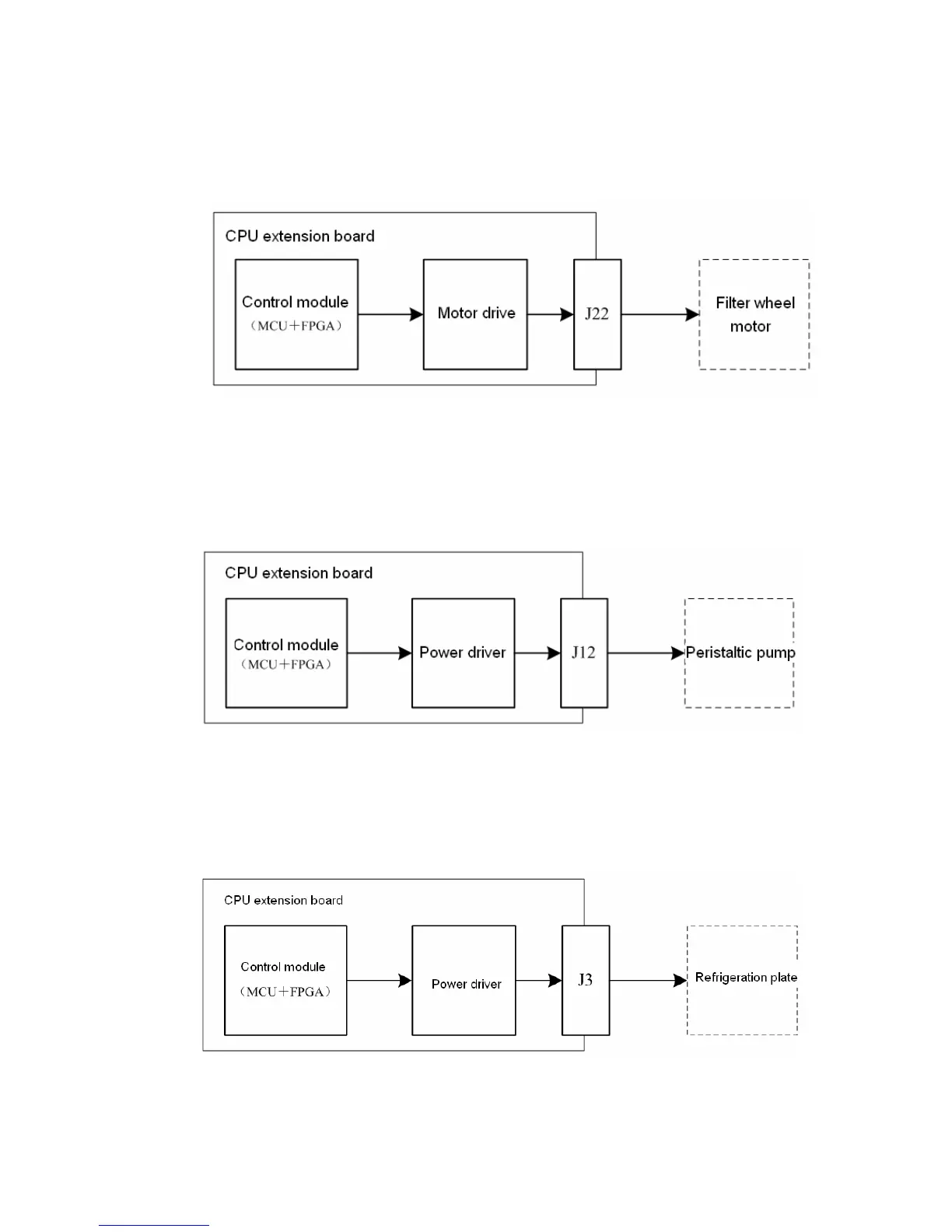
Figure 4-7 Graph of the step motor driver
The control module of the CPU extension board (including: MCU and FPGA) outputs
motor control signal, which can control the step motor of the filter wheel via step
motor driver circuit.
4.5.7 Driver of the Peristaltic Pump
Figure 4-8 Graph of the peristaltic pump driver
The control module of the CPU extension board (including: MCU and FPGA) outputs
peristaltic pump control signal, which can control the motor of peristaltic pump via
power driver circuit.
4.5.8 Driver of the Refrigeration Plate
Figure 4-9 Graph of the refrigeration plate driver
The control module of the CPU extension board (including: MCU and FPGA) outputs
motor control signal, which can control the refrigeration plate via power driver circuit.