Structure and Assembly/Disassembly of the Machine
The chip for USB interfaces controls the two USB interfaces and is connected with an
external power management chip. Each USB interface can provide maximum 500mA. If
the current exceeds 500mA, the power for USB interfaces will be cut off automatically.
2.1.1.2Transmission circuit
The transmission circuit generates the high voltage transmission pulse for exciting the
elements to generate the sound field. This system adopts the one-to-one fashion for the
transmission circuit and elements.
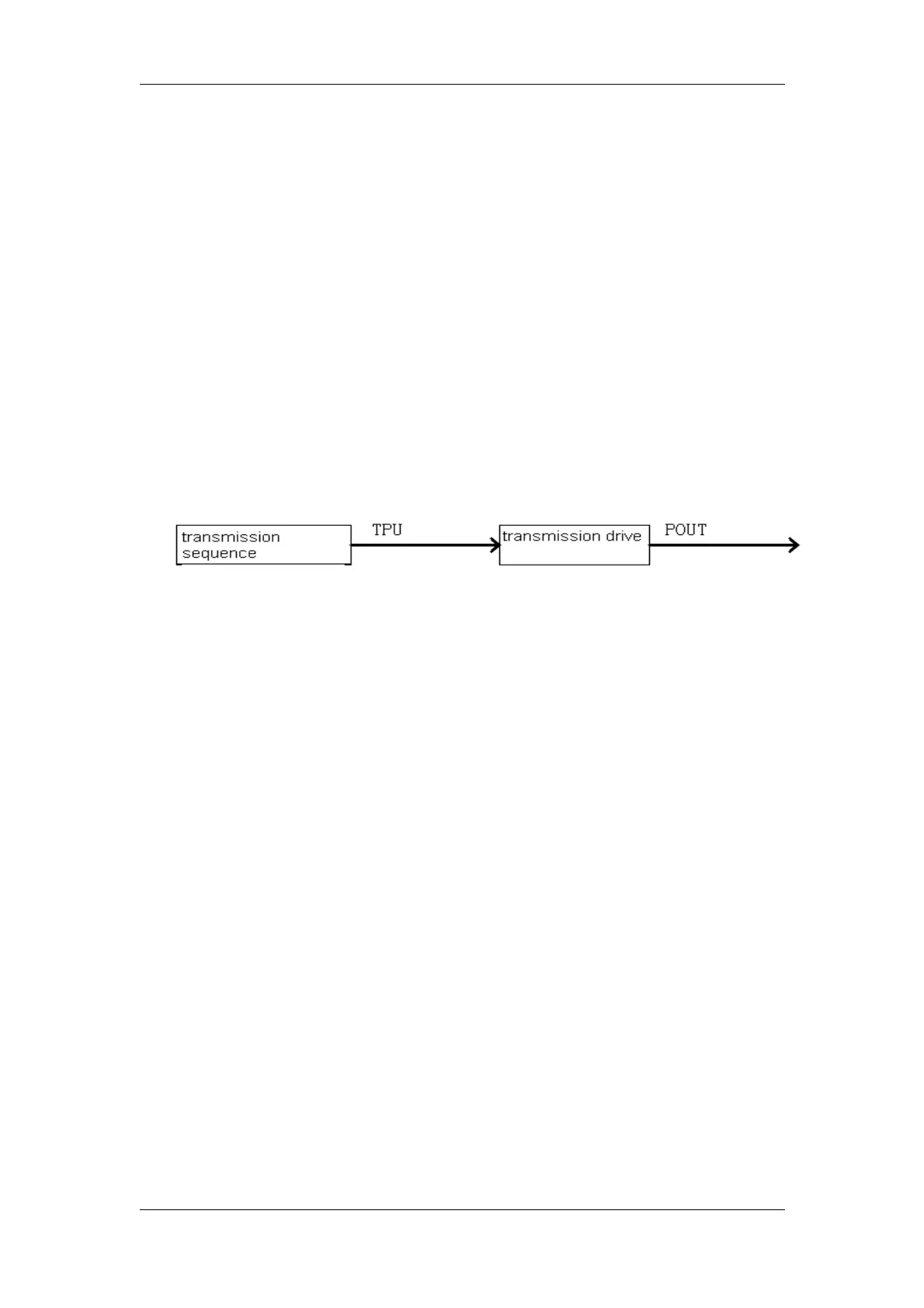
The transmission circuit is comprised of two parts: transmission sequence and
transmission drive. The transmission sequence circuit generates the low voltage
transmission pulse TPU [n..0], which passes the transmission drive and becomes the
high voltage transmission pulse POUT [n..0] for driving the elements.
Figure 3-41 the diagram of ultrasound transmission
The elements have intrinsic spectrum, and changing the spectrum of the excitation signal
can change the transmission spectrum, i.e., changing the spectrum of the transmission
pulse. For the system, two types of adjustment are designed.
One type of adjustment is to adjust the high level width of single transmission pulse. The
narrower the high level width of transmission pulse, the wider the spectrum of
transmission pulse. This type of adjustment is only used for the central frequency to
become low.
The other type of adjustment is realized by means of the transmission burst. The pulse
count determines the transmission pulse width, and the pulse repetition period
determines the central frequency of transmission pulse. The big transmission power can
realize the free movement of the central frequency, but with sacrificing the transmission
bandwidth, thus affecting the axial resolution. Therefore the pulse count is set to 2 or 3.
To improve the lateral resolution, decreasing the side lobe can increase the transmission-
DP-3300/DP-3200 Service Manual(V1.1) 3-5