Hardware Introduction
2-10
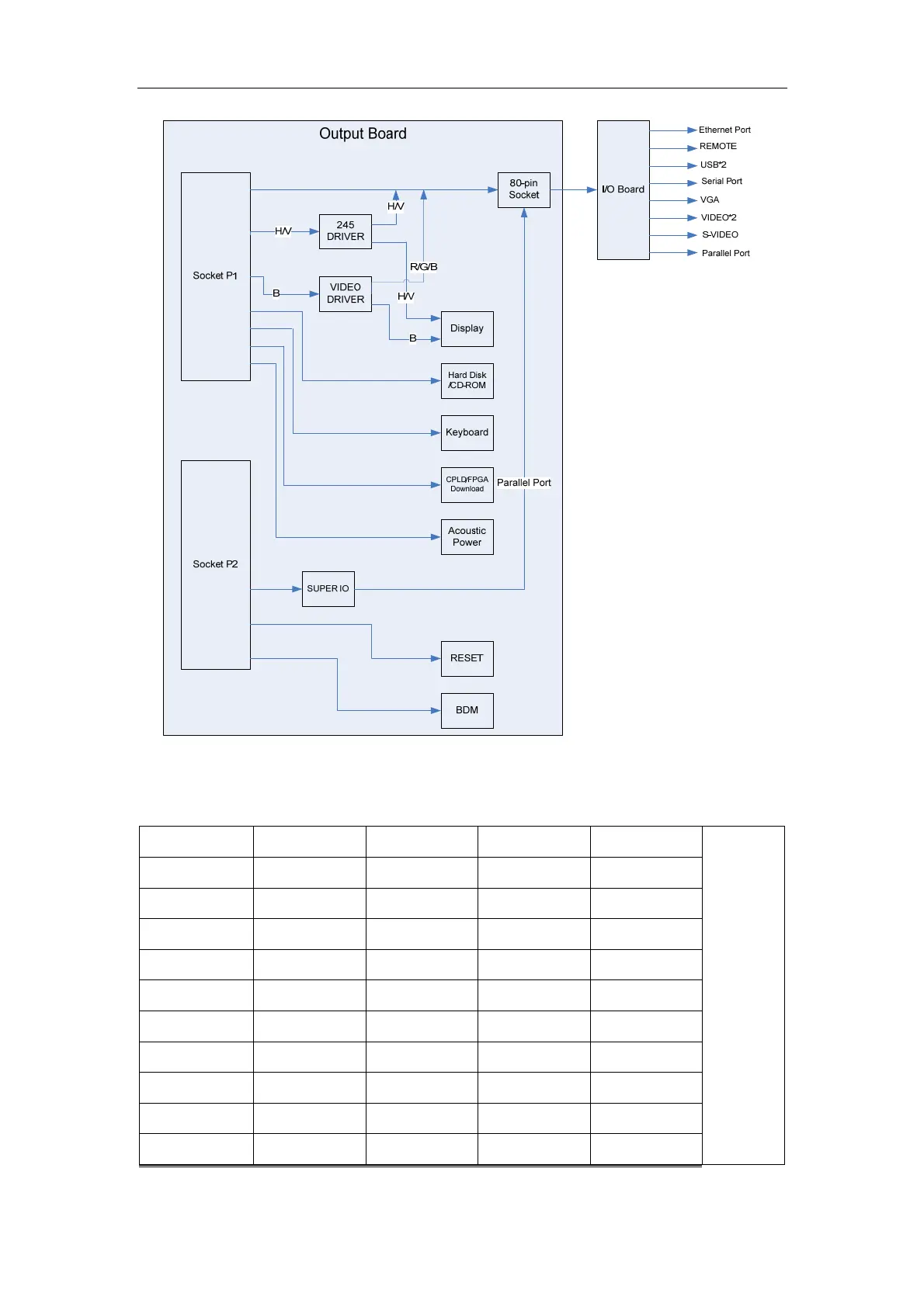
The interfaces between the output board and the main board are defined in the tables below.
CT7 TPOP TPON TPIP TPIN
P1
GND GND GND GND GND
IDE_RST IDE_D0 IDE_D1 IDE_D2 IDE_D3
GND IDE_D4 IDE_D5 IDE_D6 GND
IDE_D10 IDE_D7 IDE_D8 GND IDE_D9
IDE_D14 GND IDE_D11 IDE_D12 IDE_D13
GND IDE_D15 GND IDE_NIOW IDE_NIOR
IDE_NDMACK GND IDE_IORDY IDE_ALE GND
GND IDE_IRQ IDE_DA2 GND IDE_DA0
IDE_NCS1FX IDE_NCS3FX GND IDE_DA1 IDE_NDASP
GND GND VIEDO1 GND GND