Do you have a question about the Mindray Veta 3 and is the answer not in the manual?
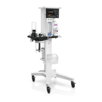
This document outlines the installation procedures for the Veta 3 and Veta 5 anesthesia systems, covering various components from the trolley to specialized gas management systems.
The initial step involves securing the main unit to the trolley. The column is inserted into the trolley base, and the trolley is then positioned to allow for tightening of the screws. This forms the foundational support for the entire system.
Tools Required:
After the trolley is assembled, the main unit is securely placed on it. This involves locking the four casters of the trolley to ensure stability. The main unit is aligned with three positioning columns on the trolley, which correspond to three locating pins. Once aligned, screws are tightened to secure the main unit in place.
Tools Required:
The CO2 absorbent canister is a critical component for gas management. To install it, the canister is rotated counterclockwise until it is firmly fixed. It is important to check the connector for any absorbent particles before installation to ensure proper sealing and function.
For the Veta 5 system, the bellows are installed in two main steps: a. The bottom ring of the bellows is attached to the bellows base, ensuring a tight connection. b. The bellows housing bayonet is aligned with the designated slots and then rotated clockwise to firmly secure it.
The breathing circuit for the Veta 5 system requires careful assembly: a. The guiding post slots of the breathing system are aligned with the guiding post of the main unit circuit connector. Screws are then used to fix the breathing circuit. b. A fastener located under the supporting board is fixed, and an inner hexagon spanner is inserted into it. c. The microswitch cable plug is inserted into its designated slot.
Tools Required:
The basket provides convenient storage. It can be hung directly on the machine's handrail or installed onto the column.
Tools Required:
This optional component enhances oxygen supply capabilities: a. The oxygen generator tray assembly is fixed to the column and trolley using screws and a fixing plate. b. The oxygen generator connector is rotated clockwise into the gas supply inlet, and the oxygen generator is connected with a tube.
Tools Required:
This optional installation provides additional utility: a. The tray or weigher (Veta 5 Only) is inserted into the screw arbor, and the screws are tightened. b. The weigher cable is connected to the communication interface (SP). c. Three silicon plugs are used to attach the cable to the column and fix it on the back of the machine.
Tools Required:
This component manages waste anesthesia gases: a. The self-prepared anesthesia gas filter canister is placed on the weigher or tray, aligning it with the groove. b. A silicone tube is used to connect the gas filter canister with the AGSS inlet pipeline connector.
This system is crucial for managing waste anesthetic gases: a. Two stop pins are rotated into the AGSS support rail, and the AGSS support rail is fixed to the side of the column with screws. b. The AGSS assembly is inserted into the AGSS support rail, and the knob is rotated tightly. The AGSS gas supply hose connects the waste gas outlet with the AGSS assembly inlet. c. For passive scavenging, the waste gas outlet is connected with the passive scavenging pipe.
Tools Required:
| Brand | Mindray |
|---|---|
| Model | Veta 3 |
| Category | Medical Equipment |
| Language | English |