EasyManua.ls Logo

Minebea CSA-522B - Connection Procedures; Terminal Allocation and Usage

Default Icon
38 pages
Print Icon
To Next Page IconTo Next Page
To Previous Page IconTo Previous Page
Loading...
3
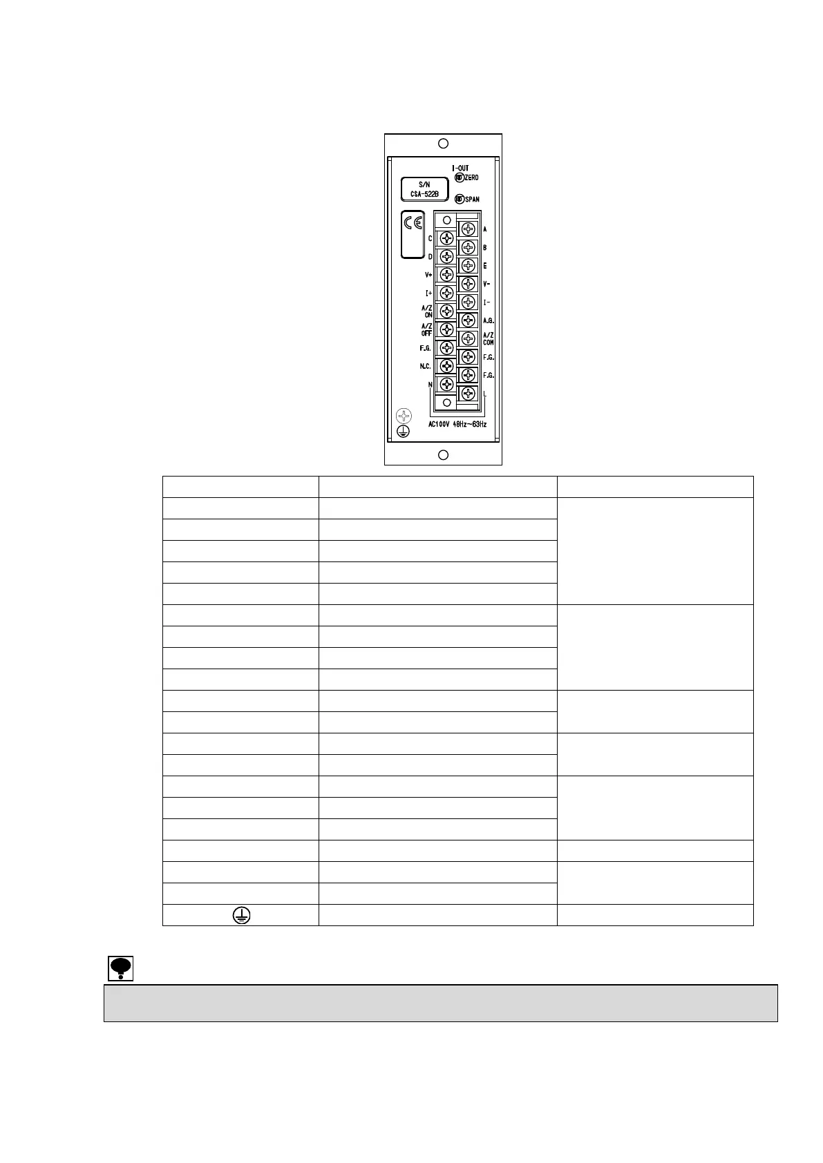
2. Connecting method
2-1. Allocation of the terminals
Name of terminal
Description
Usage
A
Bridge power supply()
Strain gage applied transducer
C
Bridge power supply ()
D
Amplifier input ()
B
Amplifier input ()
E
Shield
A.G.
Analog ground
For check
F.G.
Frame groung
F.G.
Frame groung
F.G.
Frame groung
V
Voltage output terminal()
Voltage output
V
Voltage output terminal ()
I
Current output terminal ()
Current output
I
Current output terminal ()
A/Z ON
Terminal for AUTO ZERO ON control
External control input
(Option)
A/Z OFF
Terminal for AUTO ZERO OFF control
A/Z COM
Common for controling auto zero
N.C.
No use
Do not use.
L
Power supply input terminal (L)
Power supply
N
Power supply input terminal (N)
Protective earth terminal
The terminal F.G. and the terminal E are connected internally.
The terminal A.G. and the terminal V-OUT (-), the terminal I-OUT (-) are connected internally.

Related product manuals