4. Function and operation
4-1. Setting of ZERO adjustment
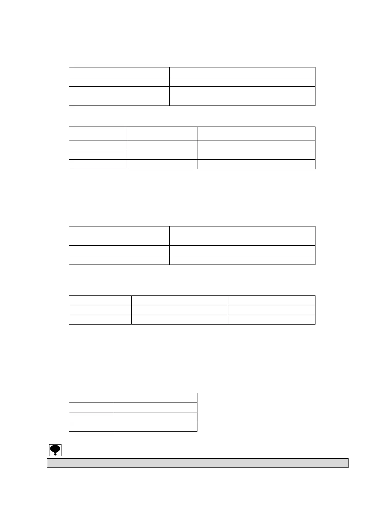
Zero point can be changed by ZERO coarse control switch and ZERO fine control trimmer.
ZERO coarse control switch
Variable range by ZERO fine control trimmer
Approx.0.3 mV/V to Approx.0.6 mV/V
Approx. -0.3 mV/V to Approx.0.3 mV/V
Approx.-0.6 mV/V to Approx.-0.3 mV/V
4-2. Setting of GAIN adjustment
Sensitivity can be changed by GAIN coarse control switch and GAIN fine control trimmer.
GAIN coarse
adjustment switch
Variable range by GAIN
fine control trimmer
Approx. 500 times to Approx. 2 000 times
Approx. 750 times to Approx. 3 000 times
Approx. 250 times to Approx. 1 000 times
The variable range above mentioned is input conversion to get the output of DC10V.
(When the bridge power supply voltage is set as DC10V.)
4-3. Settng of CALIB value
The voltage or the current corresponding to the CALIB set value (input conversion value) is
output.
Input conversion value to be output
4-4. Setting of frequency response
Frequency response can be selectable.
The changeover of 1 Hz and 30 Hz at FILTER ON is selected by DIP switch on circuit board.
When both 1 and 2 of DIP1 on the printed cirsuit board turns OFF, 1 Hz is selected.
(The standard is 30 Hz. The setting is that both 1 and 2 of DIP1 turns ON.)
4-5. Setting of bridge power supply voltage
The bridge power supply voltage is selectable.
Please select the voltage value less than the maximum rated voltage of a strain gage applied
transducers.
Bridge power supply voltage
● Please execute the calibration again when the bridge power supply voltage is changed.