MISC INFORMATION BATTERY REPLACEMENT
13
MISCELLANEOUS INFORMATION
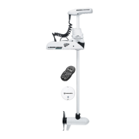
• The five buttons are for PROP ON/OFF, STEER LEFT, STEER RIGHT, INCREASE SPEED AND DECREASE
SPEED.
• Pressing the PROP ON/OFF button will turn the propeller on or off. The button does not need to be held down.
(Press the button once to turn the motor ON; press button a second time to turn it OFF.)
• Pressing either STEERING button will cause the motor to turn in the desired direction as long as the button is held
down. If a steering button is held for more than seven seconds, the steering will automatically stop.
• Pressing and releasing the INCREASE SPEED or DECREASE SPEED buttons will cause the speed to increase
or decrease by one level. The speed is adjustable from level 0-10. At level 0, the prop will not turn.
• An audible beep is heard for each step change in speed. Attempting to go higher than speed 10 or lower than
speed 0 will result in the speed not changing and no beep will be heard. See the Audio Mode section for more
information.
• If the receiver senses no foot pedal or remote operation for 1 hour, the remote speed setting is automatically set
to zero. This could help prevent unintentional activation of the propeller if the prop on /off remote button is inad-
vertently pressed or bumped while in storage.
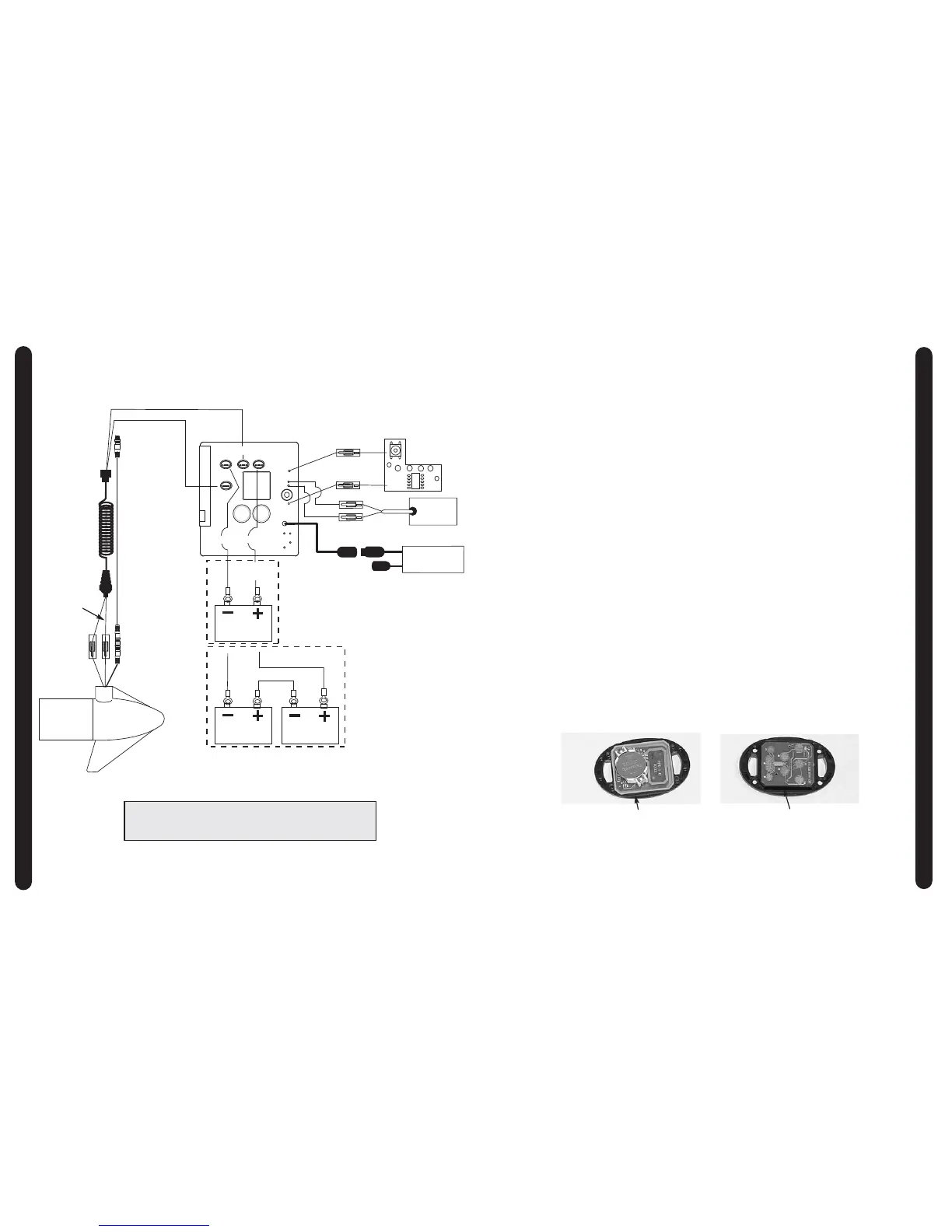
BATTERY REPLACEMENT
THE REPLACEMENT BATTERY MUST BE A MODEL CR2032 COIN CELL TYPE. IT IS STRONGLY
RECOMMENDED THAT A NAME BRAND BATTERY IS USED.
To replace the battery, follow these steps:
1.) Temporarily ground yourself by touching a grounded metal object in order to discharge any static elec-
tricity in your body.
2.) Remove the four screws on the bottom of the remote case.
3.) Separate the case halves to access the circuit board.
4.) Pull back the retaining fingers of the battery holder to remove the battery (underside of circuit board.)
5.) Install the new battery with the positive (+) side of the battery facing up (away from the circuit board).
Ensure battery is snapped securely in place.
6.) Reassemble the remote. Note that the alignment peg in the remote case must line up with the cor-
responding alignment hole in the circuit board. Also note that the keypad must be positioned so that
the buttons are over the end of the circuit board opposite from the alignment peg and hole. Reinstall
the four case screws and tighten them as required.
BATTERY
ALIGNMENT PEG
WIRING DIAGRAMS
8
12-24 VOLT MODELS
NOTE:
1. BATTERY 2 AND CONNECTING WIRE USED FOR 24V APPLICATIONS ONLY
2. UNIVERSAL SONAR 2 WIRES APPLICABLE TO US2 MOTORS ONLY