minnkota.johnsonoutdoors.com | 77 ©2023 Johnson Outdoors Marine Electronics, Inc.
PARTs DIAgRAM & PARTs LIsT
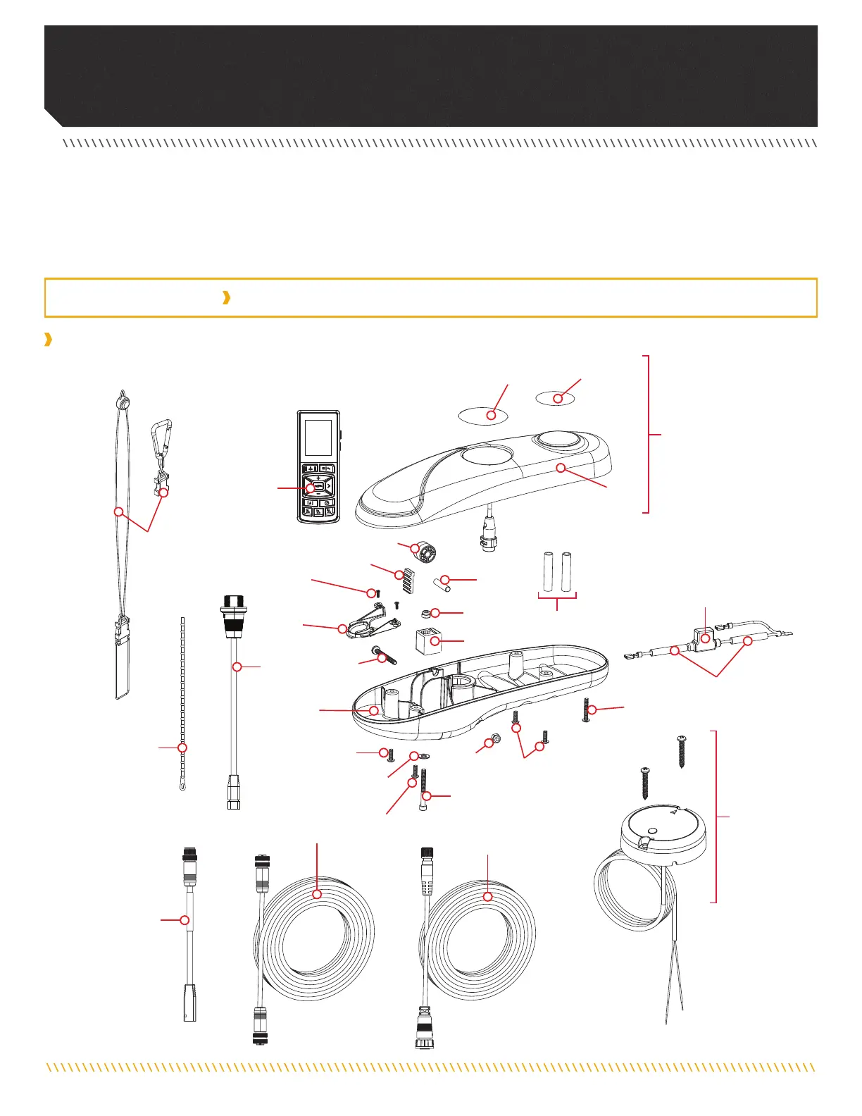
Control Head Parts Diagram
ULTERRA - 80/112 LBS THRUST - 24/36 VOLT - 45"/60" SHAFT
The parts diagram and parts list provide Minn Kota® WEEE compliance disassembly instructions. For more information about where you
should dispose of your waste equipment for recycling and recovery and/or your European Union member state requirements, please
contact your dealer or distributor from which your product was purchased. Tools required, but not limited to: flat head screwdriver,
Phillips screwdriver, socket set, pliers, wire cutters.
ULTERRA CONTROL HEAD
A
50
6
30
38
20
18
22
14
B
2
26
16
42
24
42
42
8
10
40
34
36
54
52
4
48
46
44
28
12
32
 Loading...