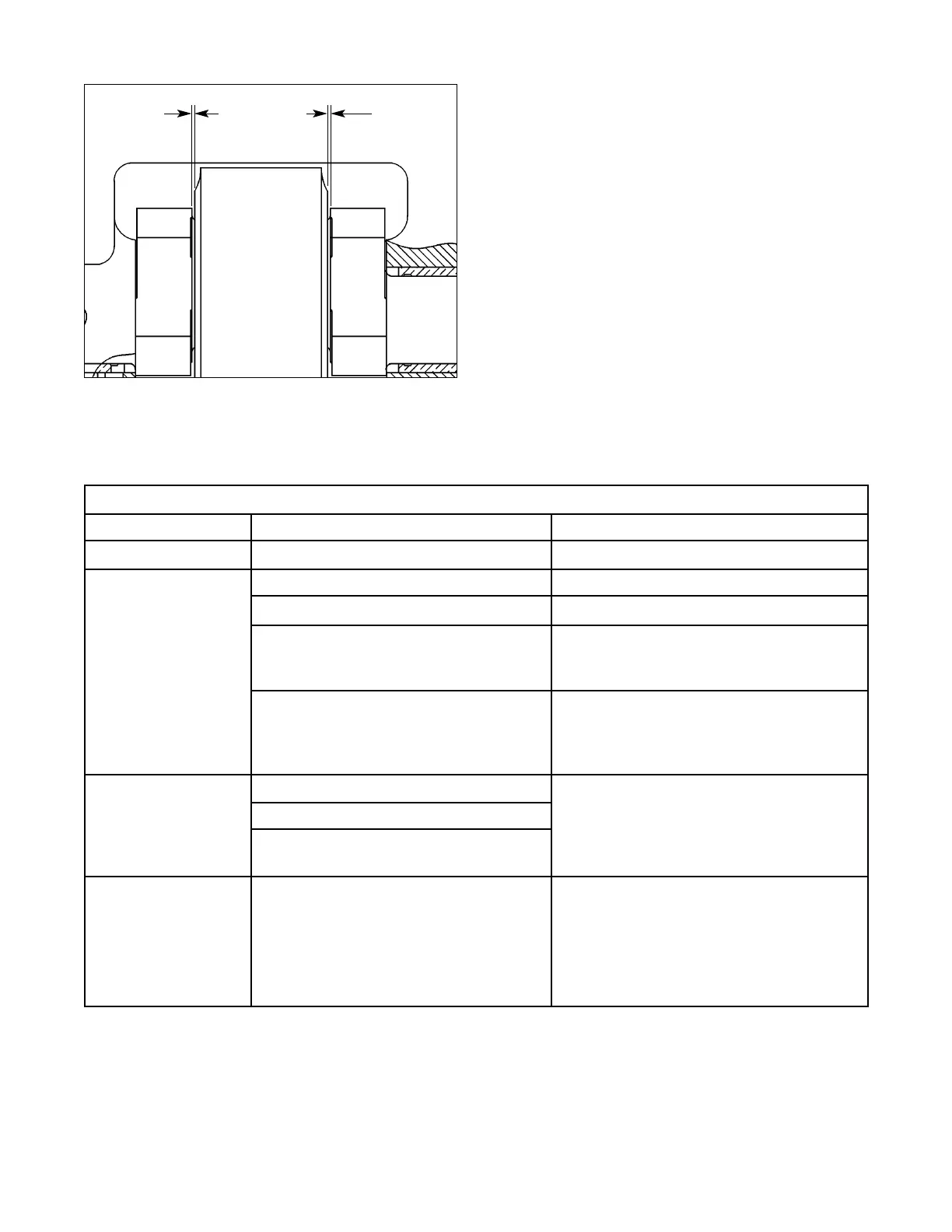
13. While an assistant maintains pressure on the
slide, check clearance between the slide and the
untightened gib. Total gib clearance should not
exceed 0.003” to 0.004” (0.076 to 0.101 mm).
14. If gib clearance is satisfactory, relieve pressure on
the slide and tighten gib mounting bolts and lock
adjusting screws. If gibs require adjustment,
adjust the gibs following the procedure listed
under “To Adjust Gib Clearance,” page F-3.
15. When gib clearance is set, reinstall any covers
previously removed and tighten their associated
mounting screws securely.
F - 11
.03”
.03”
Figure 11F. Checking connection to crankshaft clearance.
Factors Affecting Parallelism And Vertical Movement
DUE TO POSSIBLE CAUSE CORRECTION
Frame distorted. 1. Press not level (in twist). Level press carefully.
Gibs not adjusted
properly or gibs
are damaged.
1. Sliding surfaces worn due to usage. Set gibs as explained on page F-2.
2. Improper setting of gibs. Set gibs as explained on page F-2.
3. Gibs damaged (probably due to
lack of oil).
Repair or replace gib and wear plate, if
necessary. (Problem cannot be
corrected by adjustment.)
4. Gibs damaged (due to excessive
counterbalance pressure).
Repair or replace gib and wear plate if
necessary. Make certain counterbal-
ance pressure is set properly to avoid
future damage.
Worn or damaged
bearings.
1. Normal wear.
Check bearing clearances. (See page
G-4.) Replace bushings if clearance is
excessive. Eliminate the overload or
off-center loading condition.
2. Overheating or lack of lubrication.
3. Overloading or frequent off-center
loading.
Slide adjusting
nuts not turning
equally.
1. Slide adjustment bevel gears loose
on shaft or cross shaft brackets
loose.
Check condition of slide adjusting cross
shaft and bevel gear assembly. Replace
keys and tighten the set screws or cap
screws as necessary. Make certain slide
parallelism is correct before locking
components in the final position.