Module Settings
30
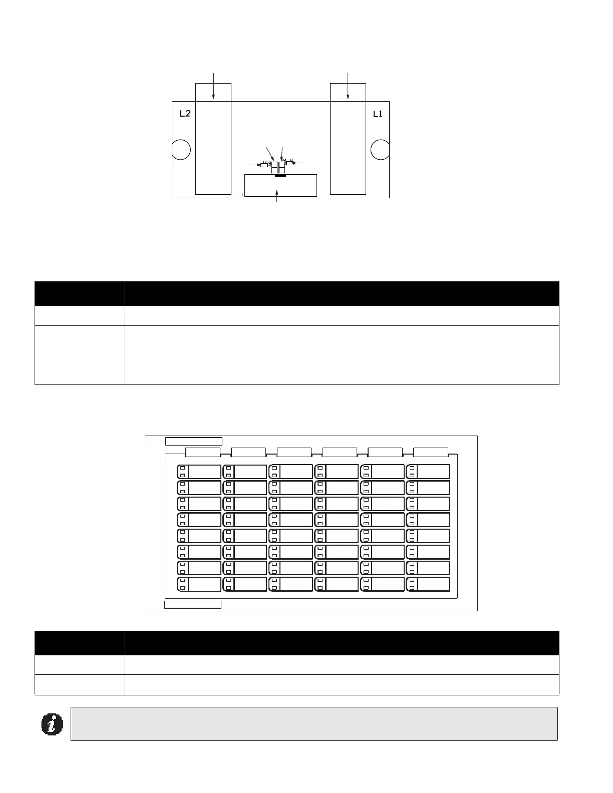
Figure 12: FOM-2000-UM Fiber Optic Network Module
One of these modules is required at each panel where fiber optics will be used between them. The FOM-2000-UM
will be mounted over the FNC-2000 Network board (over the field wiring terminals) with two #6 Phillips screws and
two Hex spacers.
Table 2: FOM-2000-UM Fiber Optic Network Module Cable Connection
RAX-1048TZDS Zone Display Module
Figure 13: Zone Display Module ( RAX-1048TZDS)
Table 3: RAX-1048TZDS Zone Display Module Cable Function
Connector Function
P1 P1 cable attaches to P10 of the FNC-2000 Fire Network Controller Module.
JW1
JW2
JW1 must be on (closed) if an optical module is installed in L1. JW2 must be on (closed) if an
optical module is installed in L2.
If there is no optical module in L1, remove the jumper from JW1. If there is no optical module in
L2, remove the jumper from JW2.
Connector Function
P1 P1 Cable connects to P2 of previous display module.
P2 P2 Cable connects to P1 of next display module
Note: The zone display module comes with laser printer-compatible slide-in paper labels for zone labelling.
XTXRXTXR
A ediSB ediS
Connect cable to P10 on the FNC-2000
Bay for optical module
Bay for optical module
JW1
JW2
I2
I1
P1