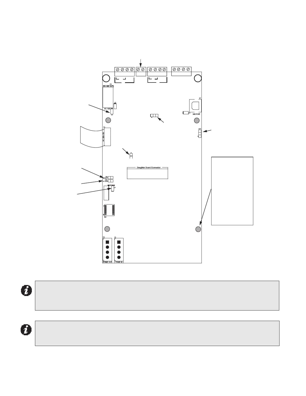
42
Mounting holes, terminals for wiring, cable connections and jumper locations on the ALCN-792MISO Quad Loop
Adder module are shown in Figure 26 below.
Figure 26: ALCN-792MI SO Quad Loop Adder Module
Wiring The Addressable Loops
There are two addressable loops present on this board that are wired in the same manner as shown in
the wiring diagrams beginning with Figure 32. Although these drawings show only Loop 1; Loop 2 is
wired in the same way as Loop 1 is.
Notes for ALCN-792MI SO:
• All circuits are power limited and must use type FPL, FPLR, or FPLP power limited cable.
• Loop wiring: maximum loop resistance is 40 ohms total. These lines power-limited and fully supervised.
+ - + -
SS + - + -
ALARM OUT
B
A
A
B
COM (-)
LOOP 1 LOOP 2
SHIELD
RS-485
P3
P2
P6
P1
ADDRESS
DIP SWITCH
Loop 1
Active LED
Loop 2
Active LED
Four shaded
mounting holes are
for Daughter board
ALCN-792D
Top 2 holes and
bottom 2 holes are
used for the ALCN-
792MISO Quad Loop
Adder module
mounting
DIP SWITCHES ARE FOR THIS
BOARD’S ADDRESS. SW1-1
IS THE LEAST SIGNIFICANT
DIGIT (BINARY). ACTIVE
POSITION IS ON.
P4
SW1
POWER CABLE
(OUT)
POWER CABLE
(IN)
JW2 - leave closed
JW1 - leave open
Green ashing
RS-485 heartbeat
LED
Green ashing
heartbeat LED for on
board processor
OUT
Daughter Board
Connector
RS-485
IN
USB PORT
(Factory use only)
JW4
JW3
JW6
8
1
NOT USED
JTag
Port