QBB-5001(R) Expansion Audio Cabinet Module Placement
84
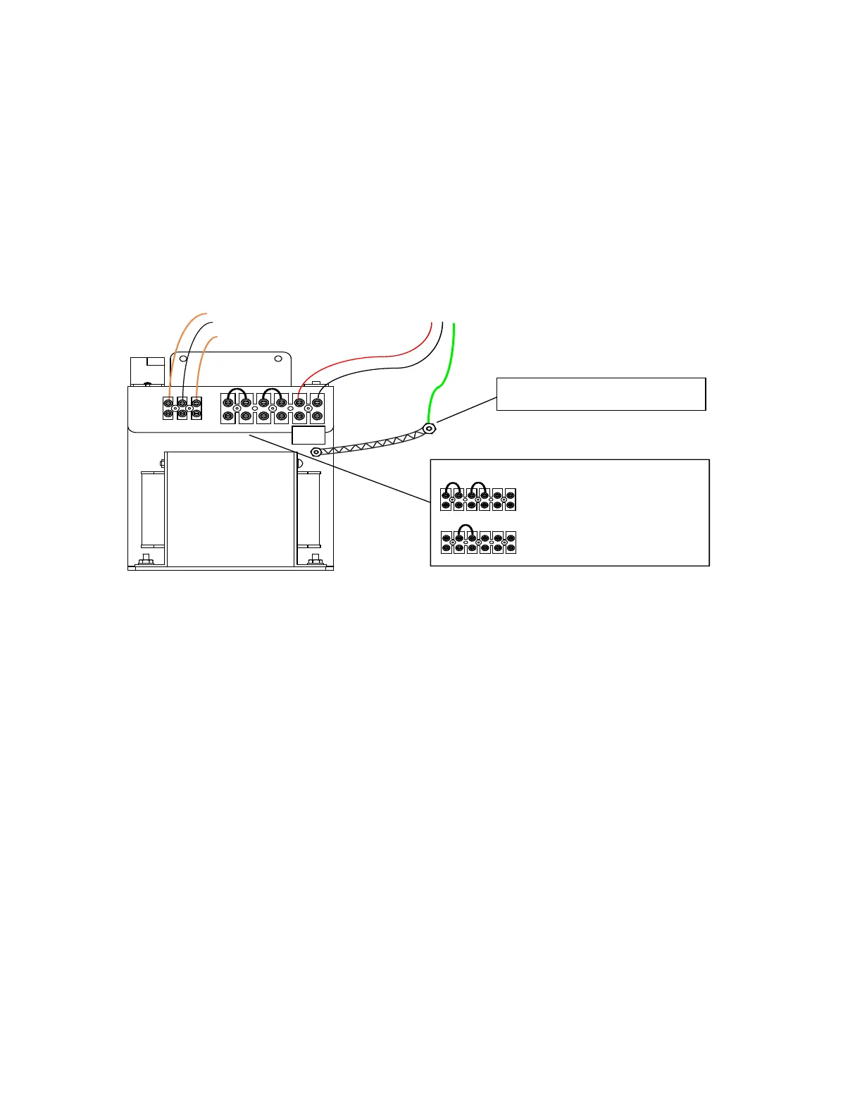
QPS-5000N Pow er Supply Connection
Two jumpers are provide as shown in figure below for 120 VAC connection. For 240 VAC application, remove both
jumpers and replace one jumper between the two middle terminals. The two terminals on the right are N (neutral), L
(live) for AC voltage connection. The three terminals on the left are connected from the QMB-5000N motherboard as
orange-white-orange (left to right) in that order.
Figure 54: QPS-5000N Power Supply Wiring Diagram
Orange- White-Orange
Wires connected to
QMB-5000B Motherboard
120 VAC or
240 VAC
Live (Black)
Ground
Earth Ground stud in QBB-5001(R) Backbox
Neutral (White)
Connect AC ground to Earth Ground stud
located in the QBB-5001(R) Backbox.
L N
L N
L N
QPS-5000N
120 VAC Select
120/240 VAC SELECTION
OR
240 VAC Select
Default Jumper Positions
Discard unused Jumper
Ground Braid