33
5.5 FOM-2000-UM Multi Mode Fiber Optic Network Module
One of these modules is required at each panel where fiber optics will be used between them.
The FOM-2000-UM will be mounted over the FNC-2000 Network board (over the field wiring
terminals) with two #6 Phillips screws and two Hex spacers.
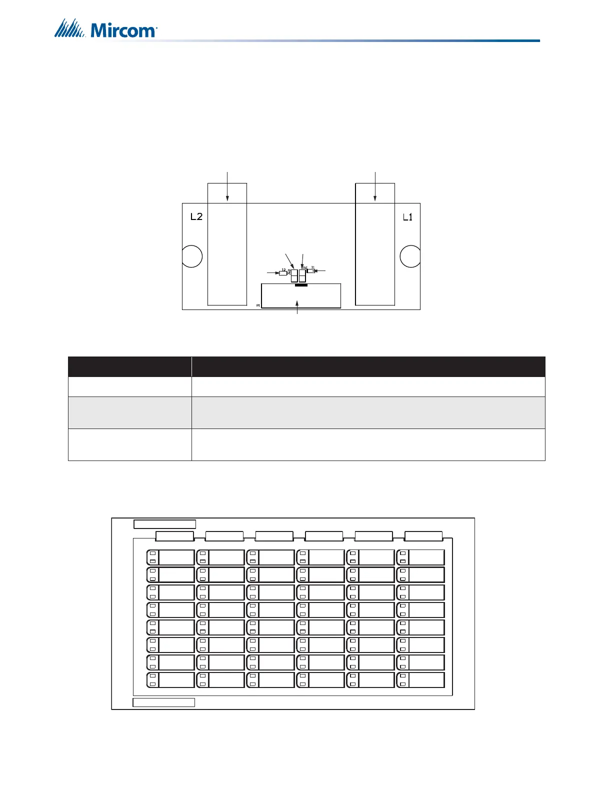
Figure 12 FOM-2000-UM Multi Mode Fiber Optic Network Module
Table 2 FOM-2000-UM Fiber Optic Network Module Cable/Jumper Connection
5.6 RAX-1048TZDS Zone Display Module
Figure 13 Zone Display Module (RAX-1048TZDS)
Connector and Jumpers Function
P1 P1 cable attaches to P10 of the FNC-2000 Fire Network Controller Module.
JW1 on FOM-2000-UM
Remover jumper JW1 if there is no optical module installed in L1 bay.
Connect jumper (closed) when installing an optical module in L1 bay.
JW2 on FOM-2000-UM
Remover jumper JW2 if there is no optical module installed in L2 bay.
Connect jumper (closed) when installing an optical module in L2 bay.
RX TX RX TX
Side B Side A
Connect to P10 on the FNC-2000
Bay for optical module
Bay for optical module
JW1
JW2
I2
I1