SW1
SW1 sets the Telephone Access controller RS-485 network address and
determines how the IP module get its IP address (if installed).
• Use DIP switches 1 to 6 to set the RS-485 network address.
Inputs 1 to 5
Input 1 Postal Lock. Input 1 connects to the Postal Lock. Activation of this
input unlocks the main door and starts the main door timer. Daily usage is
limited according to a pre-defined number.
Input 2 Fire Panel. Input 2 connects to the fire alarm panel and receives fire
notification. Activation of this input unlocks the main and auxiliary doors.
Input 3 Main Door Sense. Input 3 connects to the door sense switch.
Activation of the Main Door Sense locks the main door and resets the main
door open timer.
Inputs 4 and 5 General Purpose. Inputs 4 and 5 are general purpose inputs
that, when configured, activate a general purpose output to perform any
required function.
Connection for Connection for
Display and Display and
KeypadKeypad
Thermal KitThermal Kit
GroundGround
TerminalTerminal
P7 P7
Modem Interface Modem Interface
P4 P4
USB PortUSB Port
JW2 JW2
JW1 JW1
JW7 JW7
JW5 JW5
Aux. Door Aux. Door
Output 2 Output 2
RelayRelay
General RelayGeneral Relay
Output 3Output 3
Telephone Lines 1 to 5 Telephone Lines 1 to 5
T R
1
1
T R
5
T R
2
2
T R
3
T R
4
AC or DCAC or DC
Input DoorInput Door
StrikeStrike
Supply Supply
DC Output 1 DC Output 1
Door StrikeDoor Strike
General RelayGeneral Relay
Output 4Output 4
AC Output 1 AC Output 1
Door StrikeDoor Strike
NC
C
NO
NC C NO
Power terminals for 16 Vac Power terminals for 16 Vac
transformer use 18 gauge transformer use 18 gauge
wire (PS-4 or PS-4P)wire (PS-4 or PS-4P)
PowerPower
ON/OFF SwitchON/OFF Switch
OFF ON
- S+
INPUT
-
S+
OUTPUT
1 1 5
2
2 3 4
LED/LAMPLED/LAMP
Supply Supply
CameraCamera
Supply Supply
Microphone Microphone
Connection Connection
Speaker Speaker
Connection Connection
Inputs 1 to 5Inputs 1 to 5 RS-485RS-485
JW3 JW3
JW4 JW4
SW1 SW1
JW8 JW8
JW6 JW6
16 Guage 16 Guage
Wire Wire
P6 P6
AC Output 1
Door Strike
AC or DC Input
Door Strike Supply
NO
NC
JW8
Alternative Wiring for
Dry Contact
P5 P5
AC or DC Input Door Strike
The power for the door strike is customer supplied and provides AC or DC
power for one of the door strike outputs. The controller converts an AC
supply to a DC output. The reverse is not true. An AC door strike will not
work with a DC power supply. The maximum supply for the AC or DC Input
Door Strike is not to exceed:
• 28 VAC \ 1 A max
• 30 VDC \ 1 A max
AC Output 1 Door Strike
The AC Output Door Strike receives power from the AC Input Door Strike
supply. The AC power output remains the same as the power supplied to the
AC Input Door Strike.
DC Output 1 Door Strike
The DC Output Door Strike receives power from the AC or DC Input Door
Strike supply. When using a DC Input Door Strike supply, the DC power
output remains the same as the input.
Outputs 2 to 4
See LT-969 Telephone Access System Installation and Operation Manual.
Jumpers
JW1. Leave open. Short only when updating firmware.
JW2. Leave open. Short only when updating firmware.
JW3. Leave open. Not used.
JW4. Leave open. Not used.
JW5. Leave open. Not used.
JW6. Leave open. Not used.
JW7. Leave open. Not used.
JW8. JW8 defines the operating state of the door strike relay as normally
open or normally closed. A jumper wire connects to either the normally open
(top position for a door strike) or normally closed pin (bottom position for a
maglock).
Connections
USB. Computer connection for firmware download and configuration.
P4. TX3-MDM Modem Board connector.
P5. MD-921 IP Module connector. Only for model numbers ending with
“-A” (for example, TX3-2000-8CH-A).
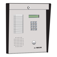
P6. Key pad and front door LCD display.
P7. Guard Phone Board connector.
RS-485
The RS-485 connection consists of an input and output terminal. Connect the
RS-485 output terminal to the RS-485 input terminal of the next controller.
Connect the last controller on the network to the RS-485 input terminal.
Refer to LT-969 for end of line resistors to be used on the first and last nodes
of network. The RS-485 terminal consists of + (positive), - (negative), and S
(Shield) connections.
Ground Terminal
The Telephone Access system is equipped with a 16 gauge electrical wire
attached to the panel chassis Ground Terminal. Do not disconnect this wire.
Attach the end of the supplied wire to a suitable grounding wire 16 gauge or
thicker. Attach the other end to the cold water ground.
Telephone Lines 1 to 5
TX3 supports full ADC and NSL telephone connectivity from a single
Telephone Access System panel or from a networked system. A single panel
supports up to five ADC and/or NSL telephone lines. Each T/R line is polarity
insensitive and can be reversed.
Note: Non-configurable PBX systems are not supported. For more
information, contact technical support at Mircom.




 Loading...