10
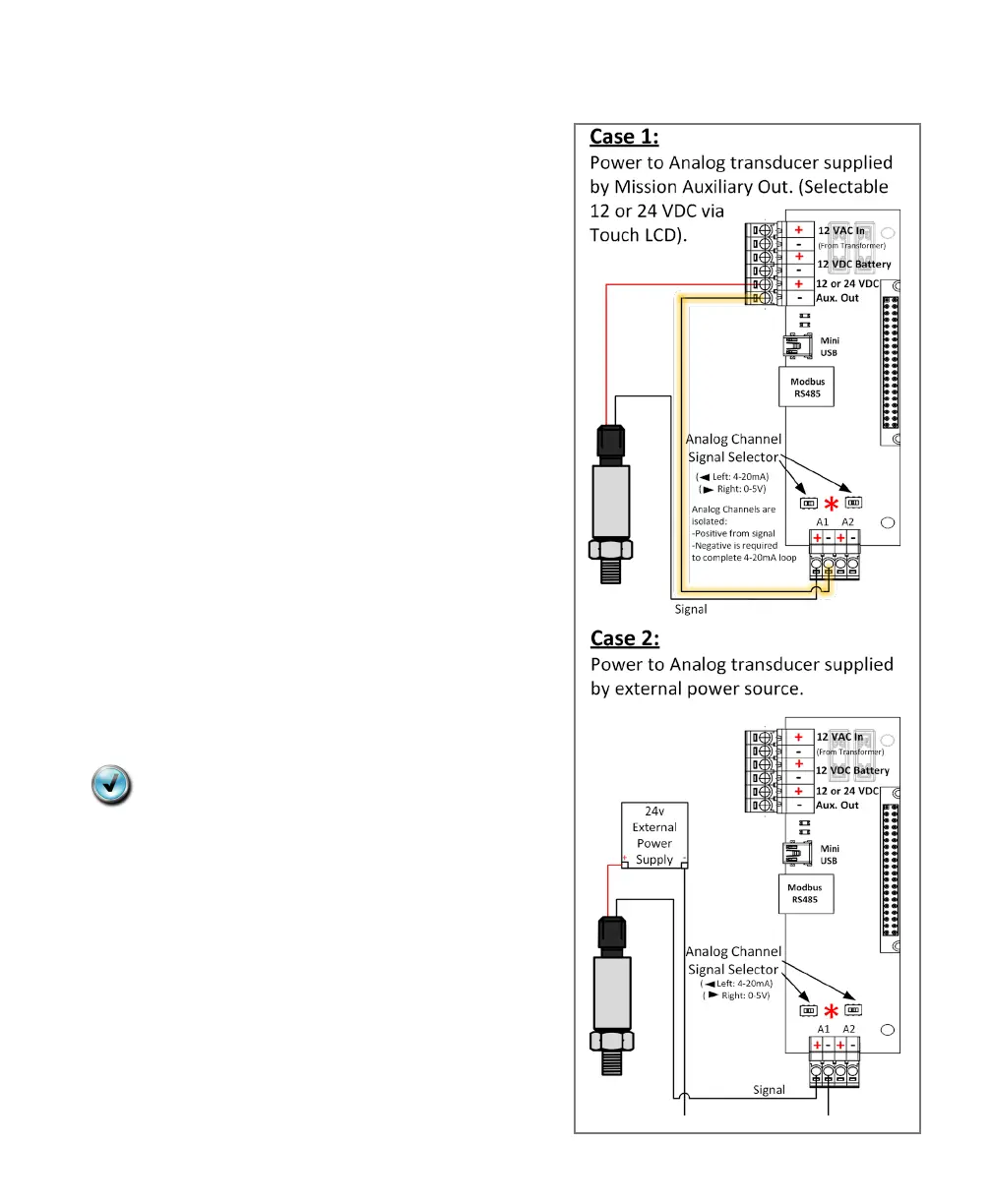
Figure 2:
Analog Input Wiring
Analog Inputs
The two onboard analog inputs of the MyDro
are isolated—they were not on the
Legacy board. If the power for the instrument
is sourced from the MyDro aux terminals an
additional conductor (highlighted in Figure 2)
from the negative terminal of the analog input
to aux is required for the loop to be complete.
The aux voltage is software selectable as 0,
12, or 24 VDC. Most analog instruments are
rated for a broad range of voltages (typically
10–30 VDC). Selecting the 24 volt option
makes voltage starvation situations much less
likely when multiple devices are present on
the current loop.
Take note of the analog jumper position on
the Legacy RTU and identify it as 0–5 volts or
4–20 mA. By default, it is set as 4–20.
See I/O Expansion section for expanded
analogs.
Note: Other components supported by
the aux-out must be rated appropriately.
For example, the ELK relay that
Mission offers has a resistor that can
be clipped for 24 VDC power.
 Loading...