5
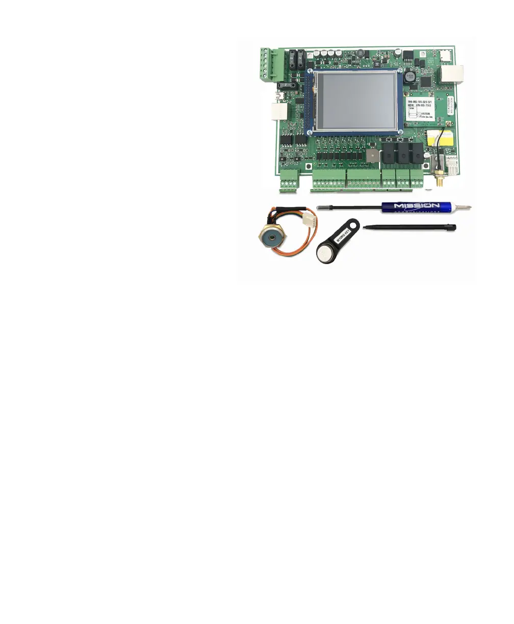
Included with RTU Upgrades
Common parts for all enclosures:
□ Printed circuit board (PCB)
□ Screwdriver
□ LCD stylus
□ Electronic key congured
to allow conguration changes
on the MyDro touchscreen
□ New antenna (PN RF430)
□ New battery (PN PW441)
□ Key reader
□ (4) #6–32 screws
□ (2) Load sensors
□ (6) Tie wraps
FlatPak:
□ Metal lid with window
□ (4) 1/4’’ standoffs
□ Knockout plug
NEMA 1:
□ Standoff mount
□ (2) Knockout plugs
□ Metal lid with window
NEMA 4
□ Plastic lid for MyDro
□ (4) 1/2’’ standoffs
□ (1) Additional key reader
NEMA 4X Solar Enclosure:
□ Plastic lid for MyDro
□ (8) 1/2’’ standoffs
□ (1) Additional key reader
Plan Your Strategy
In many cases, you will simply mount the new printed circuit board (PCB) and
rewire the conductors as they were before. This is a good time to address
aspects of installation that could be done better. Consider the best practices
listed on the following page before installation.
 Loading...