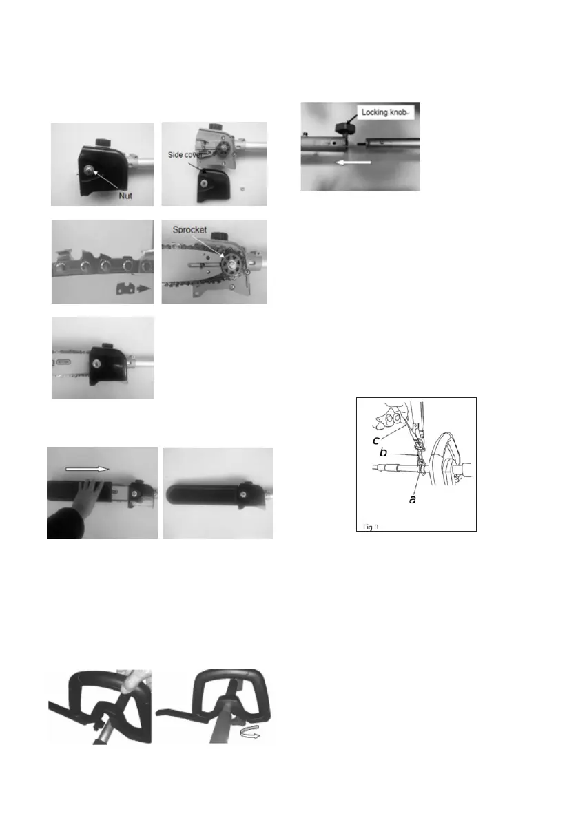
11
4. Place the saw chain around the sprocket with
teeth cuing edges facing away from the
drive sprocket along top edge of the guide bar.
( Fig 5D)
5. Insert the side cover and make sure the side
cover is securely seated in a xed way as
shown in Fig 5E.
Fig.5A
Fig.5B
Fig.5C Fig.5D
Fig.5E
GATHER UP GUIDE BAR AND CHAIN
COVER(FIG.6A 6B)
Fig.6A
Fig.6B
WARNING: For you safety and storage,
please gather up cuing guard after each
operation.
ASSEMBLE THE HANDLE
Mounting the auxiliary handle
Turn the buon lock to auxiliary handle in the
position.
ASSEMBLE SHAFT TUBE (FIG.7)
1. Insert the tube to the hole.
2. Rotation the locking knob to rm the tube.
Fig.7
ASSEMBLE SHOULDER STRAP (FIG.8)
Insert the latch (b) of the shoulder strap into the
xing device (a) - Adjust the working and cuing
position, using the dierent straps on the harness.
- In order to obtain the optimum length of the
straps, users should carry out a test and power o
the tool.
Note: The shoulder strap is equipped with a
quick-release function. Remove the latch
(c) when you need to quickly release the
straps.
 Loading...