4-290 Detailed explanation of command words
4MELFA-BASIC V
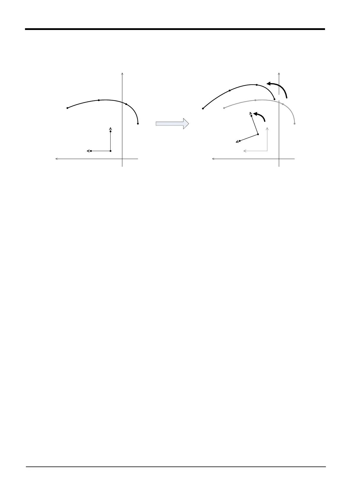
of the following figure, the pre-frame transformation reference coordinate system "Xfr-Zfr-Yfr" is defined
with position data PR1, PR2 and PR3, and the post-frame transformation reference coordinate system
"Xfc-Zfc-Yfc" is defined with position data PC1, PC2 and PC3.
Fig.4-31: Example of frame transformation
(2) The X, Y and Z axis coordinate values of each position data are used to define the coordinate system.
Other element data such as the A, B and C axis coordinate values are not used.
(3) The coordinate system cannot be calculated if the same point is found in three position data items defin-
ing the coordinate system, or if the three position data items are arranged on the same line. In this
case, error L2041 (Can’t calculate frame transformation coordinates) will occur.
(4) The reference coordinate system is not set immediately after the controller power is turned ON. The ref-
erence coordinate system is returned to the unset state with the main program’s END command or pro-
gram reset operation.
(5) The mechanism control rights (GetM command) are required to execute the SetCalFrm command.
(6) The SetCalFrm command cannot be executed in a slot for which the start conditions are ALWAYS or
ERROR. Error L3287 (Can’t use this command when start condition is ERR or ALW) will occur.
[Related instructions]
MvSpl (Move Spline)
[Related status variable]
Fram
+Xfr
+X
+Y
P11
P12
P13
P14
+Yfr
PR1
PR2
PR3
Zfr
+Xfr
+X
+Y
P11
P12
P13
P14
+Yfr
フレーム変換
Zfr
+
X
f
c
P
2
1
P
2
2
P
2
3
P
2
4
+
Y
f
c
P
C
1
P
C
2
P
C
3
Z
f
c
 Loading...


