5-440 Movement parameter
5Functions set with parameters
Standard base
coordinates
Refer to
"4.5Coordinate
system description
of the robot"
MEXBSNO Real value 1 Sets world coordinate system by specifying a base coordinate
number (base conversion).
Displays current settings, as well.
Description of set values:
0:Designates P_NBase (system's initial value). (Because
P_NBase = (0, 0, 0, 0, 0, 0), base conversion is cleared.)
1~8: Designates a set value for work coordinate systems 1
through 8 (parameters: WK1CORD through WK8CORD).
-1:Base conversion data is specified directly by a base
command or by a reference base coordinate parameter
MEXBS.
(Note: The set value "-1" is valid for read only.)
Note) The value cannot be changed during program execution or
pausing.
-1
Base coordinate
data for system
MEXSBS Real value 6 Sets the positional relationship between the world coordinate
system and the base coordinate system.
The world coordinate system and the base coordinate system
match at factory default.
This parameter is not changed by the Base command.
(X,Y,Z,A,B,C) =
0.0, 0.0, 0.0,0.0,
0.0, 0.0
Tool coordinate
data for system
MEXSTL Real value 6 Sets the initial values for the relationship between the hand tip
(control point) and the mechanical interface (hand mounting
surface).
This parameter is not changed by the Tool command or M_Tool.
(X,Y,Z,A,B,C) =
0.0, 0.0, 0.0,0.0,
0.0, 0.0
User area
Refer to
"5.8About user-
defined area"
Specify the user definition area (maximum of 32 area) and the action when the robot enters in
the area.
AREA*CS
* is 1 to 32
Integer 1 Specify the coordinate system of the user definition area *.
0: Base coordinate system (conventional compatibility)
1: Robot coordinate system
0
AREA*P1
* is 1 to 32
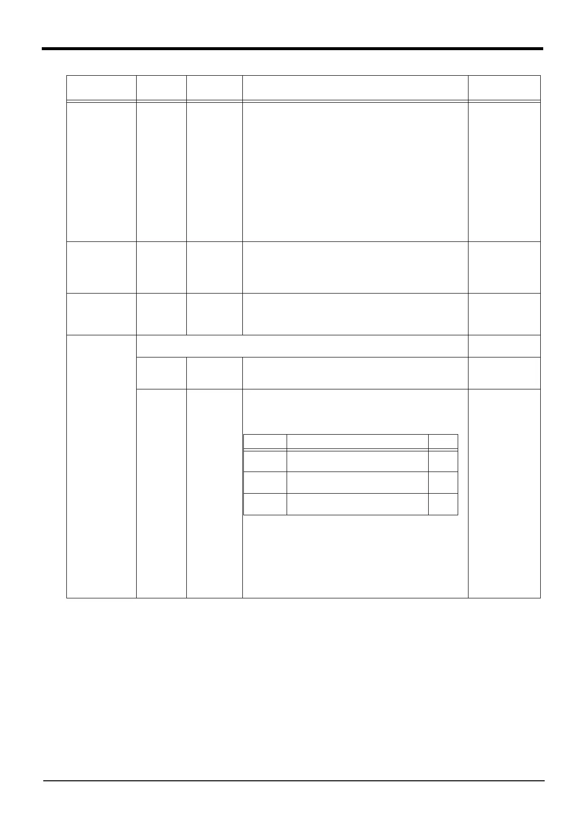
Real value 8 Designates position coordinates of the diagonal point 1 of the
user-defined area n and coordinates of posture data/additional
axes. Definitions are given, starting with the 1st element, to X, Y,
Z, A, B, C, L1, and L2 in the order listed.
<NOTES>
*Specify values in the coordinate system which was designated
by AREA*CS.
*If a posture check is not to be made, set A, B and C coordinates
to -360.
*If additional axes are used, specify elements L1 and L2.
*In regard to elements X, Y, Z, L1 and L2, defined area remains
unchanged if parameter interchange is made to AREA*P2.
(X,Y,Z,A,B,C,L1,L2)
= 0.0, 0.0, 0.0,
-360.0, -360.0,
-360.0, 0, 0
Parameter
Parameter
name
No. of arrays
No. of characters
Details explanation Factory setting
Item Details Unit
X, Y, Z
elements
Specify position coordinates of the
diagonal point 1.
mm
A, B, C
elements
Specify posture area. deg
L1, L2
elements
Specify additional axis area. mm,
deg
 Loading...


