6-564 Dedicated input/output
6External input/output functions
ERROUT Input Error No. output
request
The error number is output to the numerical
output (IODATA). After the start of inputting
this signal to the robot, wait at least 15 ms
before reading the numerical output (IODATA)
signal.
Edge 10025,
10025
-1,
-1
Output Error No. output signal The "error number output in progress" status is
output to the numerical output.
JOGENA
(Operation
right
required)
Input Jog valid input signal Jogs the designated axis in the designated
mode.
Operation takes place while this signal is ON.
Level -1,
-1
-1,
-1
Output Jog valid output signal Outputs that the jog operation is entered.
JOGM Input Jog mode input
(start No., end No.)
Designates the jog mode.
0/1/2/3/4/5 = Joint/ XYZ/ Cylindrical/ 3-axis
XYZ/ tool/Work (Ex-T)
Note) For Ex-T control or Ex-T jog, refer to
Page 677, "7.4 Ex-T control".
Level
Note3)
-1(Start bit),
-1(End bit),
-1(Start bit),
-1(End bit)
Note3)
-1(Start bit),
-1(End bit),
-1(Start bit),
-1(End bit)
Output Jog mode output
(start No., end No.)
Outputs the current jog mode.
JOGMENO
*Available soft-
ware versions
S/W Ver.
F-Q series:
R5 or later
F-D series:
S5 or later
Input Jog mechanism num-
ber input
(start No., end No.)
Designates the mechanism number.
If this parameter is not specified, mechanism
number is fixed to machine 1.
Level -1(Start bit),
-1(End bit),
-1(Start bit),
-1(End bit)
-1(Start bit),
-1(End bit),
-1(Start bit),
-1(End bit)
Output Jog mechanism num-
ber output
(start No., end No.)
Outputs the current mechanism number.
JOG+ Input Jog feed plus side for 8-
axes
(start No., end No.)
Designates the jog operation axis.
JOINT jog mode: J1, J2, J3, J4, J5, J6, J7 and
J8 axes from the start number.
XYZ jog mode: X, Y, Z, A, B, C, L1 and L2
axes from the start number.
CYLINDER jog mode: X,
θ, Z, A, B, C, L1 and
L2 axes from the start number.
3-axis XYZ jog mode: X, Y, Z, J4, J5 and J6
axes from the start number.
Tool jog mode: X, Y, Z, A, B and C axes from
the start number.
WORK jog mode (Ex-T jog mode): X, Y, Z, A,
B and C axes from the start number.
Note) For Ex-T control or Ex-T jog, refer to
Page 677, "7.4 Ex-T control".
Level
Note4)
-1,
-1
Note4)
-1,
-1
Output - -
JOG- Input Jog feed minus side for
8-axes
(start No., end No.)
Designates the jog operation axis.
JOINT jog mode: J1, J2, J3, J4, J5, J6, J7 and
J8 axes from the start number.
XYZ jog mode: X, Y, Z, A, B, C, L1 and L2
axes from the start number.
CYLINDER jog mode: X,
θ, Z, A, B, C, L1 and
L2 axes from the start number.
3-axis XYZ jog mode: X, Y, Z, J4, J5 and J6
axes from the start number.
Tool jog mode: X, Y, Z, A, B and C axes from
the start number.
WORK jog mode (Ex-T jog mode): X, Y, Z, A,
B and C axes from the start number.
Note) For Ex-T control or Ex-T jog, refer to
Page 677, "7.4 Ex-T control".
Level
Note4)
-1,
-1
Note4)
-1,
-1
Output - -
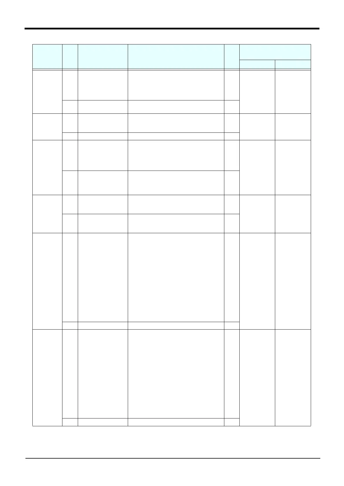
Parameter
name
Class Name Function
Signal
level
Note1)
Factory shipment signal number.
Input, output
CR7xx-Q CR7xx-D
 Loading...


