Appendix-626 Spline interpolation
7Appendix
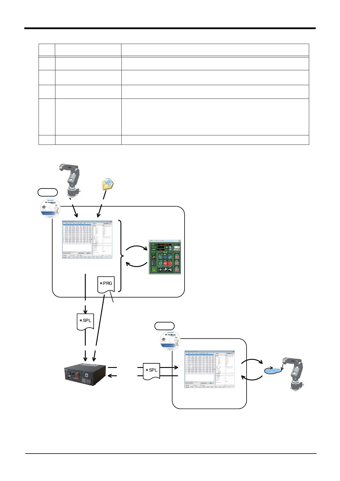
Fig.7-24:Schematic diagram of work details
2 Creating the robot program
(Chapter "7.3.6")
Create a robot program that contains the spline interpolation movement.
3 Confirming the movement
(Chapter "7.3.7")
Confirm the spline interpolation movement with the simulation function
Note1)
, and correct
the path point position and robot program as needed.
4 Saving to robot controller
(Chapter "7.3.8")
Write the robot program and spline file to the robot controller.
5 Adjustment work
(Chapter "7.3.9")
Make fine adjustments to the actual system using the RT ToolBox2 Spline File Edit screen.
(1) Using debugging operations, confirm the spline interpolation movement in the actual
system.
(2) Read the spline file to the Spline File Edit screen.
(3) Correct the path point position and path adjustment setting as needed.
(4) Write the spline file to the controller.
(5) Repeat steps (1) to (4) to create the required path, and adjust the spline file data.
6 Operation Run the robot program and execute spline interpolation.
Note1) Not supported with the RT ToolBox2 mini version.
No.
Step Work details
Create
Teach
Import
Spline File
Edit screen
Confirm
Review
Simulation
function
Generate
Write
Robot Program
Adjust
Spline File Edit screen
Actual system
Confirm
Adjust
Read
Write
Spline file
Spline file
 Loading...


