Appendix-672 Spline interpolation
7Appendix
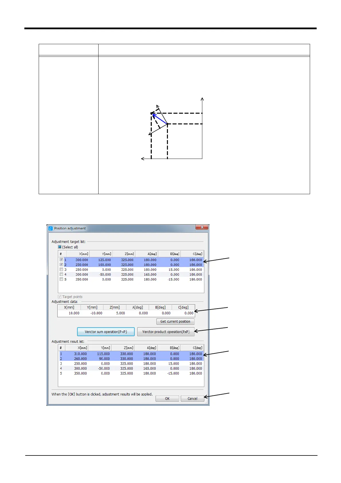
To use the position adjustment function, click the menu [Tool] → [Position adjustment]. The Position adjust-
ment screen opens when [Position adjustment] is clicked.
Fig.7-105:Position adjustment screen
The position is adjusted with the following steps.
(A) The path point data for the Spline File Edit screen currently active is displayed in the "Adjustment tar-
get list". Select and check the path point data for which the position is to be adjusted. Multiple path
point data items can be selected.
Vector product operation
(P×P)
The adjustment data values are multiplied in respect to the path point data's robot position data.
(Position after adjustment = Path point position × adjustment data)
The adjustment follows the tool coordinate system.
The configuration flag, multi-rotation flag and additional axis data are not changed from the original
value.
Adjustment method Explanation
Xw
Yw
PA
PB
P
C
.
Y
P
C
.
X
X
t
Y
t
PA:補正対象の経路点
PB:補正結果
PC:補正データ
Xt-Yt:PAにおけるツール座標の向き
ベクトル積演算(PxP)
PA: Path point for adjustment target
PB: Adjustment results
PC: Adjustment data
Xt-Yt: Orientation of tool coordinates at PA
Vector product calculation (P×P)
 Loading...


