••••••••••••••••••••••••••••••••••••••••••••••••••••••••••••••••••••••••••••••••••••••••••••••••••••••••••••••••••••••••••
Connections
17
ENGLISH
/AUTO SET UP
Connections (continued)
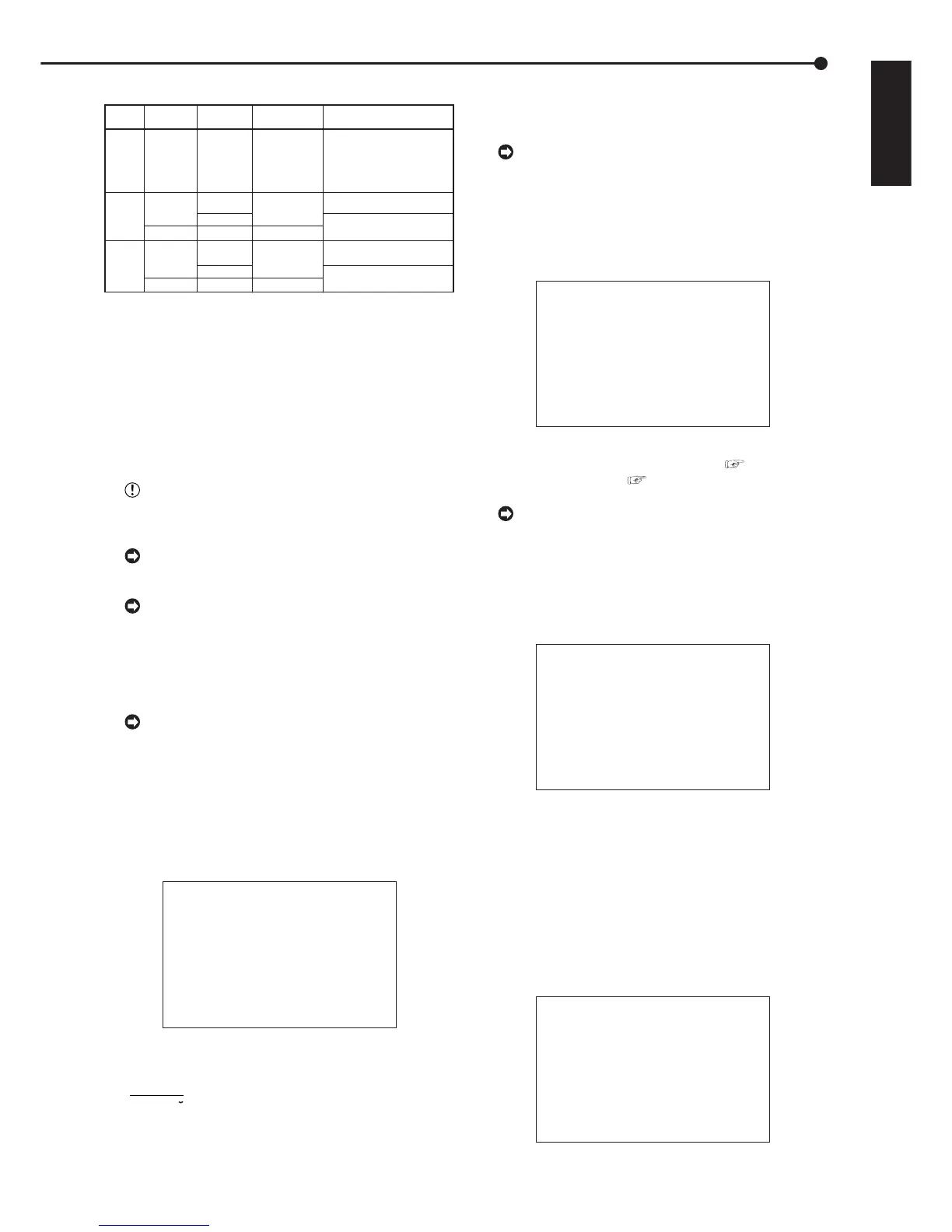
SCSI number chart
ID4 • ID5
SCSI ID
Number
0
1
3
4
5
2
Purpose
#1
HDD expansion/
HDD recording
Archive
#1
Notes
Maximum recording capacity
is 2TB per unit.
Maximum recording capacity
is 2TB per unit.
Maximum recording capacity
is 2TB per unit.
Maximum recording capacity
is 130GB per unit.
Connected
device
HDD
DDS/RDD
HDD
[ARCHIVE
•
COPY]
[ARCHIVE
•
COPY]
[HDD]
[HDD]
HDD
* RDD: Abbreviation of removable disk drive.
Select a disk drive which can eject the recording medium.
* HDD: Abbreviation of hard disk drives.
Please use those which include self-defect capabilities.
* DDS: Abbreviation of digital data storage.
Select a recording medium which uses tape.
* When hard disk drives are connected to ID0, ID1, ID2, or ID3,
the displayed estimates of recording time will include the expanded HDD.
When storage capacity is expanded to its maximum, however, there will
be instances where the times set for long recording intervals are not dis-
played correctly.
Copy
#1
Maximum recording capacity
is 130GB per unit.
DDS/RDD
HDD
HDD
When connecting a CD-R/RW as peripheral record-
ing device, set the SCSI ID No. to ID4. Use of ID5 is
not possible.
Storage capacity is indicated in gigabytes (GB).
(1GB = 1000 x 1000 x 1000 bytes.)
Storage capacity is indicated in terabytes (TB).
(1TB = 1000 x 1000 x 1000 x 1000 bytes.)
■ AUTO SET UP
AUTO SET UP is displayed, in order to set up an indispen-
sable function, when this unit is turned on for the first time.
Only when the unit is turned on for the first time,
the AUTO SET UP screen is displayed automatically. It
is not automatically displayed after next time.
1. After connect the cameras and the monitors, turn on the
MAIN switch on the rear of the unit and wait until the ACCESS
indicator is turned off, then press the POWER button on the
front.
• The <LANGUAGE SELECTION> screen is displayed. The
language of the menu can be selected in this screen.
<LANGUAGE SELECTION>
>>
LANGUAGE ENGLISH
EXECUTE
JOG :SELECT
SHUTTLE>>:EXECUTE
2. Turn the SHUTTLE ring clockwise.
• The background of the setting changes to red and flashes.
• Setting ( default : “ENGLISH” )
“ENGLISH”, “FRANCAIS”, “DEUTSCH”, “ESPAÑOL”,
“
P
y
CCK
NN
”
3. Turn the JOG dial to display the desired setting and turn the
SHUTTLE ring clockwise.
• The setting is confirmed and flashing stops.
Beware while setting the AUTO SET UP, the menu
screen can not be exited. Furthermore the screen al-
ready set can not be displayed again.
4. Turn the JOG dial to move the cursor to “EXECUTE”, and
turn the SHUTTLE ring clockwise.
• The <TIME DATE ADJUST> screen appears.
• The date/time is set in this screen.
<TIME DATE ADJUST>
>>
DAYLIGHT SAVING OFF
DAY 01
MONTH 01
YEAR 2003
TIME 00:00:00
APPLY
EXECUTE
JOG :SELECT
SHUTTLE>>:EXECUTE
5. Set the desired setting in this screen referring to “
♦
DAYLIGHT SAVING/DAYLIGHT SETTING ( see page 21)”,
“
♦
TIME DATE ADJUST ( see pages 21, 22)”.
By turning the JOG dial to the cursor to “APPLY”
and turn the SHUTTLE ring clockwise, “00:00:00” of
“TIME” will start after the moment of turning the SHUT-
TLE ring.
6. Turn the JOG dial to move the cursor to “EXECUTE”, and
turn the SHUTTLE ring clockwise.
• “PERFORM AUTO SET UP?” is displayed on the screen.
PERFORM AUTO SET UP?
>>
YES
NO
SHUTTLE>>:EXECUTE
7-1. (When not execute AUTO SET UP • • • )
Select “NO” by turning the JOG dial and turn the SHUTTLE
ring clockwise.
• “SETTING UP...” is displayed on the screen, and the unit
starts-up.
7-2. (When execute AUTO SET UP • • • )
Select “YES” by turning the JOG dial and turn the SHUTTLE
ring clockwise.
• The <CAMERA CHECK> screen appears.
• The cameras connected and the video condition can be
confirmed in this screen.
<CAMERA CHECK>
>>
EXECUTE
CHECK CAMERA CONNECTION AND
IMAGE BEFORE EXECUTE
SHUTTLE>>:EXECUTE
 Loading...