14
1 OUTLINE
1.1 Part Names
1 OUTLINE
1.1 Part Names
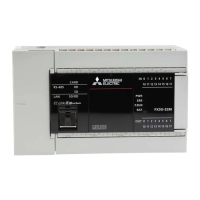
Front panel
No. Name Description
[1] DIN rail mounting hooks Hook for mounting the CPU module on a DIN rail of DIN46277 (35 mm (1.38") wide).
[2] Expansion adapter connecting
hooks
When connecting an expansion adapter, secure it with these hooks.
[3] Terminal block cover Cover for protecting the terminal block.
The cover can be opened for wiring. Keep the covers closed while equipment is running (power is on).
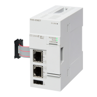
[4] Built-in Ethernet communication
connector
Connector for connection with Ethernet-compatible devices. (with cover)
For details, refer to MELSEC iQ-F FX5 User's Manual (Ethernet Communication).
[5] Top cover Cover for protecting the SD memory card slot, the RUN/STOP/RESET switch, and others.
The built-in RS-485 communication terminal block, built-in analog I/O terminal block, RUN/STOP/RESET switch,
SD memory card slot, and others are located under this cover.
[6] CARD LED Indicates whether an SD memory card can be used or not.
Lit: Can be used or cannot be removed.
Flashing: In preparation
Off: Not inserted or can be removed.
RD LED Lit when the CPU module is receiving data through built-in RS-485 communication.
SD LED Lit when the CPU module is sending data through built-in RS-485 communication.
SD/RD LED Lit when the CPU module is sending or receiving data through built-in Ethernet communication.
[7] Expansion board connector cover Cover for protecting expansion board connectors, battery, or others.
Connect the battery under this cover.
[8] Input display LED Lit when input is on.
[9] Extension connector cover Cover for protecting the extension connector.
Connect the extension cable of an extension module to the extension connector under the cover.
[10] PWR LED Indicates whether the CPU module is powered or not.
Lit: Powered
Off: Not powered or hardware error (Page 120 Checking with LEDs)
ERR LED Indicates the error status of the CPU module. (Page 120 Checking with LEDs)
Lit: Error or hardware error
Flashing: Factory default setting, error, hardware error, or resetting
Off: Operating normally
P.RUN LED Indicates the program running status.
Lit: Operating normally
Flashing: Paused
Off: Stopped or stop error
BAT LED Indicates the battery status.
Flashing: Battery error
Off: Operating normally (Page 120 Checking with LEDs)
[11] Output display LED Lit when output is on.
[1]
[7]
[8]
[9]
[10]
[11]
[2]
[2]
[3]
[3]
[4]
[5]
[6]
 Loading...