2 SPECIFICATIONS
2.10 Terminal Layout
29
2
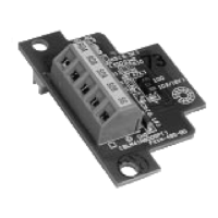
Power, input/output terminal block
■Interpretation of terminal block layout
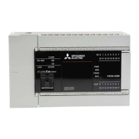
■ FX5U-32M
■FX5U-64M
• Indication of power supply terminals
[L] and [N] terminals.
For external wiring, refer to Page 79 Power Supply Wiring.
• Indication of 24 V DC service power supply
[0V] and [24V] terminals.
• Indication of input terminal
For external wiring, refer to Page 83 Input Wiring.
• Indication of output terminals connected to common (COM)
One common terminal covers 4 or 8 output points.
The output number (Y) connected to common is the range inside the thick "separation line."
For transistor output (source) type, the "COM" terminal is the "+V" terminal.
 Loading...