6
Technical Information
3
en
H
291
263
242
103
48
78
86
124
163
334
419
461
(348)
357
F
A
BE
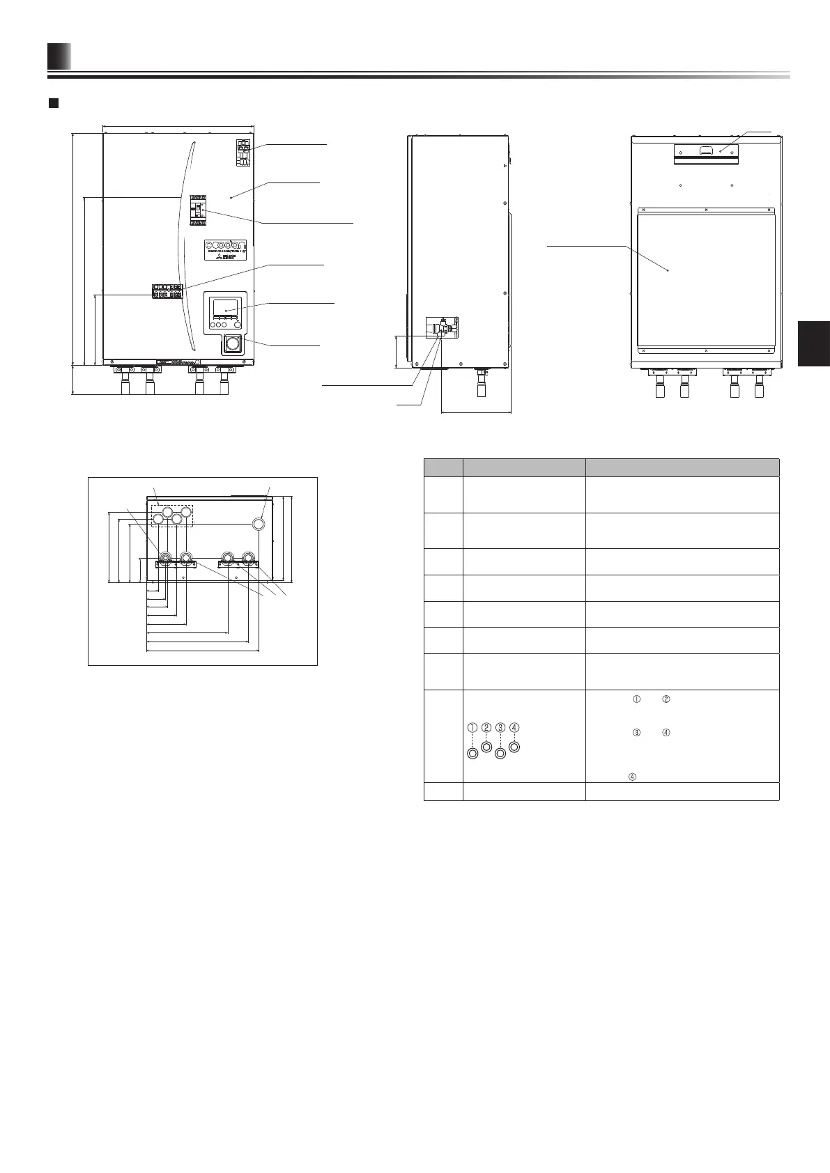
Technical Drawings
<Front>
<View from below>
<Side>
<Rear>
<EHPX> (Packaged model system)
<Unit: mm>
Letter Pipe description Connection size/type
A
Space heating/Indirect
DHW tank (primary)
RETURN connection
28mm/Compression
(EHSC/D-* and EHPX-*)
G1 nut (ERS*-*)
B
Space heating/Indirect
DHW tank (primary)
FLOW connection
28mm/Compression
(EHSC/D-* and EHPX-*)
G1 nut (ERS*-*)
C Refrigerant (Liquid)
6.35 mm/Flare (E*SD-*)
9.52 mm/Flare (E*SC-*)
D Refrigerant (Gas)
12.7 mm/Flare (E*SD-*)
15.88 mm/Flare (E*SC-*)
E
Flow connection FROM
heat pump
28 mm/Compression (EHPX-*)
F
Return connection TO heat
pump
28 mm/Compression (EHPX-*)
G
Discharge pipe (by install-
er) from pressure relief
valve
G1/2” female (valve port within hydrobox
casing)
H
Electrical cable inlets
For inlets and , run high-voltage wires
including power cable, indoor-outdoor
cable, and external output wires.
For inlets
and , run low-voltage
wires including external input wires and
thermistor wires.
For a wireless receiver (option) cable,
use inlet
.
I Drain socket
O.D. ø20
<Table 3.4>
530
(242)
G1/2
800
578
242
100±5
110
AUTO AIR VENT
FRONT PANEL
EARTH LEAKAGE BREAKER
TERMINAL BED
MAIN CONTROLLER
MANOMETER
PRESSURE RELIEF VALVE
BACK PANEL SUPPORT
HOOK