Home
Mitsubishi Electric
Controller
MR-JN-10A
Mitsubishi Electric MR-JN-10A User Manual
4
of 1
of 1 rating
480 pages
Give review
Manual
Specs
To Next Page
To Next Page
Loading...
SH(NA)030086ENG-D(1906)MEE
  
Printed in Japan
Specifications are subject to change without notice.
MODEL
MODEL
CODE
General-Purpose AC Servo
MODEL (Servo Amplifier)
MR-JN-
â–¡
A
General-Purpose Interface Servo Amplifier
JN Series
HEAD OFFICE: TOKYO BLDG MARUNOUCHI TOKYO 100-8310
JN Series
MR-JN-
â–¡
A Instruction Manual
D
D
MODEL (Servo Motor)
HF-KN
â–¡
HF-KP
â–¡
G1/G5/G7
HG-KR
â–¡
G1/G5/G7
INSTRUCTION MANUAL
2
Table of Contents
Safety Instructions
2
About processing of waste
8
COMPLIANCE WITH EC DIRECTIVES
8
CONFORMANCE WITH UL/CSA STANDARD
8
About the manuals
9
About the wires used for wiring
9
U.S. customary units
9
Introduction
10
1. Operation and setting
11
2. Startup
12
3. Troubleshooting at startup
20
4. Tough drive function
23
CONTENTS
25
1. FUNCTIONS AND CONFIGURATION
32
1.1 Introduction
32
1.2 Function block diagram
34
1.3 Servo amplifier standard specifications
37
1.4 Function list
39
1.5 Model code definition
41
1.6 Combination with servo motor
41
1.7 Parts identification
42
1.8 Configuration including auxiliary equipment
43
2. INSTALLATION
44
2.1 Installation direction and clearances
45
2.2 Keep out foreign materials
46
2.3 Cable stress
47
2.4 Inspection items
47
2.5 Parts having service lives
48
3. SIGNALS AND WIRING
50
3.1 Input power supply circuit
51
3.2 I/O signal connection example
53
3.2.1 Position control mode
53
3.2.2 Internal speed control mode
55
3.2.3 Internal torque control mode
56
3.3 Explanation of power supply system
57
3.3.1 Signal explanations
57
3.3.2 Power-on sequence
57
3.3.3 CNP1 and CNP2 wiring method
59
3.4 Connectors and signal arrangements
62
3.5 Signal explanations
65
3.6 Detailed description of the signals
71
3.6.1 Position control mode
71
3.6.2 Internal speed control mode
74
3.6.3 Internal torque control mode
77
3.6.4 Position/speed control change mode
80
3.6.5 Internal speed/internal torque control change mode
81
3.6.6 Internal torque/position control change mode
82
3.7 Alarm occurrence timing chart
83
3.8 Interfaces
84
3.8.1 Internal connection diagram
84
3.8.2 Detailed description of interfaces
85
3.8.3 Source I/O interfaces
88
3.9 Treatment of cable shield external conductor
89
3.10 Connection of servo amplifier and servo motor
90
3.10.1 Connection instructions
90
3.10.2 Power supply cable wiring diagrams
91
3.11 Servo motor with an electromagnetic brake
92
3.11.1 Safety precautions
92
3.11.2 Setting
92
3.11.3 Timing charts
93
3.11.4 Wiring diagrams (HF-KN seriesHF-KPG1/G5/G7HG-KRG1/G5/G7 servo motor)
95
3.12 Grounding
97
4. PARAMETERS
98
4.1 Basic setting parameters (No. PA [ ] [ ] )
99
4.1.1 Parameter list
99
4.1.2 Parameter write inhibit
100
4.1.3 Selection of control mode
101
4.1.4 Selection of regenerative option
101
4.1.5 Selection of the tough drive function
102
4.1.6 Number of command input pulses per servo motor revolution
103
4.1.7 Electronic gear
104
4.1.8 Auto tuning
108
4.1.9 In-position range
109
4.1.10 Torque limit
110
4.1.11 Selection of command input pulse form
111
4.1.12 Selection of servo motor rotation direction
112
4.1.13 Encoder output pulses
113
4.2 Gain/filter parameters (No. PB [ ] [ ] )
116
4.2.1 Parameter list
116
4.2.2 Detail list
118
4.2.3 Position smoothing
126
4.3 Extension setting parameters (No. PC [ ] [ ] )
127
4.3.1 Parameter list
127
4.3.2 List of details
129
4.3.3 Alarm history clear
136
4.3.4 Drive recorder function
137
4.4 I/O setting parameters (No. PD [ ] [ ] )
141
4.4.1 Parameter list
141
4.4.2 List of details
142
4.4.3 Using forward/reverse rotation stroke end to change the stopping pattern
151
5. DISPLAY AND OPERATION SECTIONS
152
5.1 Overview
152
5.2 Display sequence
153
5.3 Status display
154
5.3.1 Display transition
155
5.3.2 Display examples
156
5.3.3 Status display list
158
5.4 Diagnostic mode
160
5.5 Alarm mode
162
5.6 Point table mode
164
5.6.1 Point table transition
164
5.6.2 Point table mode setting screen sequence
165
5.6.3 Operation example
166
5.7 Parameter mode
168
5.7.1 Parameter mode transition
168
5.7.2 Operation example
169
5.8 External I/O signal display
171
5.9 Output signal (DO) forced output
174
5.10 Test operation mode
175
5.10.1 Mode change
175
5.10.2 JOG operation
176
5.10.3 Positioning operation
177
5.10.4 Motor-less operation
179
5.10.5 Forced tough drive operation
180
5.11 One-touch tuning
180
6. GENERAL GAIN ADJUSTMENT
182
6.1 One-touch tuning
182
6.1.1 One-touch tuning procedure
183
6.1.2 Display transition and operation procedure of the one-touch tuning
184
6.1.3 Precautions for one-touch tuning
188
6.2 Gain adjustment methods
189
6.3 Auto tuning mode 1
191
6.3.1 Overview
191
6.3.2 Auto tuning mode 1 basis
192
6.3.3 Adjustment procedure by auto tuning
193
6.3.4 Response level setting in auto tuning mode 1
194
6.4 2-gain adjustment mode
195
6.5 Manual mode
196
7. SPECIAL ADJUSTMENT FUNCTIONS
200
7.1 Tough drive function
200
7.1.1 Overload tough drive function
200
7.1.2 Vibration tough drive function
201
7.1.3 Instantaneous power failure tough drive function
203
7.2 Machine resonance suppression function
205
7.2.1 Function block diagram
205
7.2.2 Adaptive filter II
205
7.2.3 Machine resonance suppression filter
207
7.2.4 Advanced vibration suppression control
208
7.2.5 Low-pass filter
212
7.3 Gain changing function
212
7.3.1 Applications
212
7.3.2 Function block diagram
213
7.3.3 Parameters
214
7.3.4 Gain changing procedure
216
8. TROUBLESHOOTING
218
8.1 Alarms and warning list
218
8.2 Remedies for alarms
220
8.3 Remedies for warnings
241
9. DIMENSIONS
248
9.1 Servo amplifier
248
9.2 Connector
250
10. CHARACTERISTICS
252
10.1 Overload protection characteristics
252
10.2 Power supply capacity and generated loss
253
10.3 Dynamic brake characteristics
255
10.3.1 Dynamic brake operation
255
10.3.2 The dynamic brake at the load inertia moment
256
10.4 Cable flexing life
257
10.5 Inrush currents at power-on of main circuit and control circuit
257
11. OPTIONS AND PERIPHERAL EQUIPMENT
258
11.1 Cable/connector sets
258
11.1.1 Combinations of cable/connector sets
259
11.1.2 Encoder cable/connector sets
264
11.1.3 Motor power supply cables
274
11.1.4 Motor brake cables
276
11.2 Regenerative options
278
11.3 Junction terminal block MR-TB26A
282
11.4 MR Configurator/MR Configurator2
284
11.4.1 About engineering software
284
11.4.2 Precautions for using USB communication function
285
11.5 Selection example of wires
286
11.6 Molded-case circuit breakers, fuses, magnetic contactors
289
11.7 Power factor improving AC reactor FR-HAL
290
11.8 Relays (recommended)
290
11.9 Noise reduction techniques
291
11.10 Earth-leakage current breaker
297
11.11 Circuit protector
299
11.12 EMC filter (recommended)
299
11.13 Surge protector (recommended)
300
11.14 MR-HDP01 manual pulse generator
302
12. SERVO MOTOR
304
12.1 Introduction
304
12.1.1 Rating plate
304
12.1.2 Parts identification
304
12.1.3 Electromagnetic brake
305
12.1.4 Servo motor shaft shapes
307
12.2 Installation
308
12.2.1 Installation direction
309
12.2.2 Precautions for load remove
310
12.2.3 Permissible load for the shaft
311
12.2.4 Protection from oil and water
311
12.2.5 Cable
312
12.2.6 Inspection
312
12.2.7 Life
313
12.2.8 Machine accuracies
313
12.3 Connectors used for servo motor wiring
314
12.3.1 Selection of connectors
314
12.3.2 Wiring connectors (Connector configurations A B C)
315
12.4 Connector dimensions
316
12.5 HF-KN series servo motor
318
12.5.1 Model definition
318
12.5.2 Standard specifications
319
12.5.3 Electromagnetic brake characteristics
321
12.5.4 Servo motors with special shafts
322
12.5.5 Connector installation
323
12.5.6 Outline drawings
324
12.5.7 USA/Canada compliance
329
12.6 HF-KP series servo motor (Order accepted until May 31, 2019)
330
12.6.1 Model definition
330
12.6.2 Specifications
331
12.6.3 Electromagnetic brake characteristics
333
12.6.4 Servo motor with a reduction gear
334
12.6.5 Connector installation
339
12.7 HG-KR series servo motor
341
12.7.1 Model definition
341
12.7.2 Standard specifications
342
12.7.3 Electromagnetic brake
345
12.7.4 Geared servo motors
346
12.7.5 Mounting connectors
350
13. POSITIONING MODE
352
13.1 Selection method of each operation mode
352
13.2 Signals
353
13.2.1 I/O signal connection example
353
13.2.2 Connectors and signal arrangements
354
13.2.3 Signal explanations
355
13.2.4 Detailed description of the signals
362
13.3 Automatic operation mode for point table method
366
13.3.1 What is automatic operation mode?
366
13.3.2 Automatic operation using point table
368
13.4 Automatic operation mode for program method
379
13.4.1 What is automatic operation mode for program method?
379
13.4.2 Programming language
380
13.4.3 Basic setting of signals and parameters
395
13.4.4 Program operation timing chart
396
13.5 Manual operation mode
397
13.5.1 JOG operation
397
13.5.2 Manual pulse generator operation
398
13.6 Home position return mode
400
13.6.1 Outline of home position return
400
13.6.2 Selection of home position return mode
401
13.6.3 Dog type home position return
402
13.6.4 Count type home position return
405
13.6.5 Data set type home position return
407
13.6.6 Stopper type home position return
408
13.6.7 Home position ignorance (Servo-on position as home position)
410
13.6.8 Dog type rear end reference home position return
411
13.6.9 Count type front end reference home position return
413
13.6.10 Dog cradle type home position return
415
13.6.11 Home position return automatic return function
417
13.7 Parameters
418
13.7.1 Basic setting parameters (No. PA )
419
13.7.2 Gain/filter parameters (No. PB )
424
13.7.3 Extension setting parameters (No. PC )
426
13.7.4 I/O setting parameters (No. PD )
429
13.7.5 Positioning setting parameters (No. PE )
431
13.8 Point table setting method
437
13.9 Program setting method
439
13.10 Single-step feed usage in the test operation mode
442
APPENDIX
446
App. 1 Parameter list
446
App. 2 Servo motor ID codes
452
App. 3 Signal layout recording paper
452
App. 4 Status display block diagram
453
App. 5 Compliance with global standards
455
REVISION
465
Warranty
479
4
Based on 1 rating
Ask a question
Give review
Questions and Answers:
Need help?
Do you have a question about the Mitsubishi Electric MR-JN-10A and is the answer not in the manual?
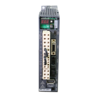
Ask a question
Mitsubishi Electric MR-JN-10A Specifications
General
Model
MR-JN-10A
Type
Servo Amplifier
Protection Class
IP20
Series
MR-JN
Rated Output
0.1kW
Input Voltage
200V
Interface
Analog Input
Related product manuals
Mitsubishi Electric MR-JN-40A
480 pages
Mitsubishi Electric MR-J3-10B
225 pages
MR-J5-G Series
216 pages
Melservo-J5 MR-J5 Series
446 pages
MELSERVO-J4 MR-J4 A Series
396 pages
Mitsubishi Electric -MR-CV
120 pages
Mitsubishi Electric MR-E-20A
310 pages
MR-E A Series
310 pages
EZMOTION MR-E Super MR-E-10A-QW003
326 pages
EZMOTION MR-E Super MR-E-70A-QW003
326 pages
Mitsubishi Electric MHK2
12 pages
Mitsubishi Electric MELSEC FX3U
1000 pages