EasyManua.ls Logo

Mitsubishi Electric MUZ-FH18NAH2 User Manual

Mitsubishi Electric MUZ-FH18NAH2
58 pages
To Next Page IconTo Next Page
Page #1 background imageLoading...
Page #1 background image
SERVICE MANUAL
Models
OUTDOOR UNIT
Indoor unit service manual
MSZ-FH•NA Series (OBH683)
NOTE:
RoHS compliant products have <G> mark on the spec name plate.
HFC
utilized
R410A
No. OBH684
REVISED EDITION-C
PARTS CATALOG (OBB684)
MUZ-FH06NA
MUZ-FH09NA
MUZ-FH12NA
MUZ-FH06NAH
MUZ-FH09NAH
MUZ-FH12NAH
Please void OBH684 REVISED EDITION-B.
Revision C:
• MUZ-FH06NA, MUZ-FH09/12NA-
1
, MUZ-
FH18NA2, MUZ-FH06NAH, MUZ-
FH09/12NAH-
1
and MUZ-FH18NAH2
have been added.
MUZ-FH06NA
MUZ-FH09NA
MUZ-FH09NA
-
1
MUZ-FH12NA
MUZ-FH12NA
-
1
MUZ-FH15NA
MUZ-FH18NA
MUZ-FH18NA2
MUZ-FH06NAH
MUZ-FH09NAH
MUZ-FH09NAH
-
1
MUZ-FH12NAH
MUZ-FH12NAH
-
1
MUZ-FH15NAH
MUZ-FH18NAH
MUZ-FH18NAH2
CONTENTS
1. TECHNICAL CHANGES ······························2
2. PART NAMES AND FUNCTIONS ··················3
3. SPECIFICATION ········································4
4. OUTLINES AND DIMENSIONS ·····················6
5. WIRING DIAGRAM ·····································8
6. REFRIGERANT SYSTEM DIAGRAM ··········· 14
7. DATA······················································ 16
8. ACTUATOR CONTROL ····························· 27
9. SERVICE FUNCTIONS ······························ 28
10. TROUBLESHOOTING ······························· 29
11. DISASSEMBLY INSTRUCTIONS ················· 51
Question and Answer IconNeed help?

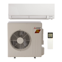
Do you have a question about the Mitsubishi Electric MUZ-FH18NAH2 and is the answer not in the manual?

Mitsubishi Electric MUZ-FH18NAH2 Specifications

General IconGeneral
TypeHeat Pump
Cooling Capacity18, 000 BTU/h
Heating Capacity21, 600 BTU/h
Seasonal Energy Efficiency Ratio (SEER)20.5
RefrigerantR-410A
Voltage208/230V
Operating Temperature (Cooling)14°F to 115°F
Operating Temperature (Heating)-13°F to 75°F
Power Supply1 Phase, 60 Hz
Sound Level (dB)49 dB

Summary

Technical Changes

New Models Added

Lists newly added outdoor unit models to the service manual.

Data

Troubleshooting

10-1. Cautions on Troubleshooting

Important safety precautions and initial checks before troubleshooting.

10-2. Failure Mode Recall Function

Procedure to recall memorized failure modes for diagnosis.

10-4. Trouble Criterion of Main Parts

Specifies resistance and voltage criteria for checking major components.

A How to check inverter/compressor

Step-by-step guide to check the inverter and compressor for faults.

B Check of open phase

Procedure to check for open phase issues in the inverter output.

D Check of compressor winding

Method to measure compressor winding resistance to identify shorts or opens.

F Check of compressor start failure

Steps to diagnose and resolve compressor start-up failures.

G Check of outdoor thermistors

Instructions for checking the resistance of various outdoor thermistors.

Check of inverter P.C. board

Procedures to diagnose issues with the inverter P.C. board, including fuse and LED checks.

M How to check miswiring and serial signal error

Guide to identify and resolve miswiring and serial communication errors.

Disassembly Instructions

6. Removing the compressor and 4-way valve

Detailed procedure for removing the compressor and 4-way valve for FH15/FH18 models.

Related product manuals