EasyManua.ls Logo

Mitsubishi Electric PK-4FLD User Manual

Mitsubishi Electric PK-4FLD
48 pages
To Next Page IconTo Next Page
Page #1 background imageLoading...
Page #1 background image
TECHNICAL & SERVICE MANUAL
CONTENTS
1. TECHNICAL CHANGES·······················2
2. COMBINATION OF INDOOR
AND OUTDOOR UNITS········2
3. PART NAMES AND FUNCTIONS········2
4. SPECIFICATIONS·································5
5. DATA·····················································9
6. OUTLINES AND DIMENSIONS··········12
7. WIRING DIAGRAM·····························15
8.
REFRIGERANT SYSTEM DIAGRAM
······16
9. OPERATION FLOW-CHART··············17
10. MICROPROCESSOR CONTROL·······20
11. TROUBLESHOOTING ························29
12. DISASSEMBLY PROCEDURE···········33
13. PARTS LIST········································36
14. OPTIONAL PARTS·····························42
Indoor unit
[ Model names ] [ Service Ref. ]
2000, 2001 2000 2001
PK-2.5FLD
PK-2.5FLD PK-2.5FLD
1
PK-2.5FLD
2
PK-3FLD
PK-3FLD PK-3FLD
1
PK-3FLD
2
PK-4FLSD
PK-4FLD PK-4FLSD
1
PK-4FLSD
2
No. OC232
REVISED EDITION-A
2000
Indoor unit
Wall Mounted
Series PK
TEMP
ON / OFF
NOT AVAILABLE
AM
PM
AM
PM
˚C
REMOTE CONTROLLER
PK-P2.5FLD
1
, PK-P3FLD
1
,
PK-P4FLSD
1
, PK-P2.5FLD
2
,
PK-P3FLD
2
and PK-4FLSD
2
are added in REVISED
EDITION-A.
Please void OC232.
This manual does not cover
the following outdoor units.
When servicing them,
please refer to the service
manual No.OC127
REVISED EDITION-A,
OC187 and this manual in
a set.
[ Service Ref. ]
(OC127 REVISED
EDITION-A)
PU-2.5VJA
2
, PU-2.5NJA
1
,
PU-3NJA
1
, PU-4VLJSA
2
,
PU-4YJSA
3
, PU-4TJSA
2
(OC187)
PU-3VJC, PU-3YJC
SPLIT-TYPE, AIR CONDITIONERS
PK-2.5FLD2
PK-3FLD2
PK-4FLSD2
PK-2.5FLD, PK-2.5FLD1
PK-3FLD, PK-3FLD1
PK-4FLSD, PK-4FLSD1
OC232--1.qxp 01.10.1 9:17 PM Page 1
Question and Answer IconNeed help?

Do you have a question about the Mitsubishi Electric PK-4FLD and is the answer not in the manual?

Mitsubishi Electric PK-4FLD Specifications

General IconGeneral
Cooling Capacity4.0 kW
Heating Capacity4.5 kW
Power Source220-240V, 50Hz
RefrigerantR410A
TypeWall Mounted

Summary

Technical Changes and Model Updates

Model Series and Revisions

Details new model additions and changes in the Series PK line, referencing revised editions.

Indoor and Outdoor Unit Compatibility

Unit Combination Chart

Table showing compatible indoor and outdoor units for various series and service references.

Indoor Unit Part Identification

Key Indoor Unit Components

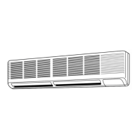
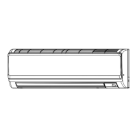
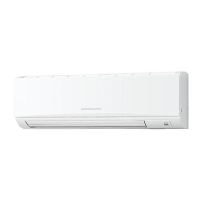
Identifies and describes the function of primary indoor unit parts like air intake and outlet.

Technical Specifications Overview

Standard Unit Specifications

Comprehensive technical data for indoor and outdoor units, including electrical and physical characteristics.

Performance Data and Correction Factors

Cooling Capacity Performance Tables

Detailed tables of cooling capacity based on varying temperature conditions for 50Hz operation.

Unit Dimensions and Outlines

Remote Controller Physical Dimensions

Illustrations and measurements for the physical size and layout of the remote controllers.

Indoor Unit Physical Dimensions

Detailed diagrams showing the size, mounting points, and piping access for the indoor unit.

Wiring Diagrams and Connections

Wiring Diagram and Component Symbols

Visual representation of electrical connections and a legend for all symbols used in the diagrams.

Refrigerant System Diagrams

Refrigerant Flow and Component Layout

Diagrams illustrating the refrigerant circuit, including the path of flow and major components.

Operation Flowcharts

Main Operation Sequence

Flowchart outlining the primary operational steps from power on to mode selection.

Cooling and Dry Operation Logic

Flowcharts detailing the control logic and sequences for cooling and dry modes.

Microprocessor Control System

Control System Overview

General explanation of the microprocessor control, covering remote, indoor, and outdoor unit interactions.

Indoor Unit Control Functions

Detailed explanation of various indoor unit control modes: Cool, Dry, Fan, Timer, Test Run, Emergency.

Unit Configuration and Settings

Information on jumper wire functions, dip switch settings, and remote controller pairing procedures.

Troubleshooting and Diagnostics

Self-Diagnostic Function Usage

Guide on performing self-diagnostics using the remote controller to identify error codes and malfunctions.

Common Troubles and Causes

Lists common problems like unit stoppage, vane issues, and wiring faults with their causes and checks.

Troubleshooting Specific Issues

Addresses causes for outdoor unit failure, wiring errors, and outdoor unit operational checks.

Component Testing Procedures

Procedures for testing key components like thermistors, motors, and transformers using electrical testers.

Disassembly Procedures

Indoor Unit Component Removal

Step-by-step instructions with illustrations for safely disassembling the indoor unit's main parts.

Parts Lists and Identification

Structural Parts Identification

List of structural components for PK-2.5/3 models with part numbers and quantities.

Electrical Components List

List of electrical parts, including motors, controllers, and sensors, with part numbers for various models.

Optional Parts and Accessories

Refrigerant Piping and Adapters

Information on optional refrigerant pipes, timer adapters, and multiple remote controller adapters.

Remote Controller and Timer Setup

Details on centralized remote controller functions, connection methods, and program timer installation.

Related product manuals