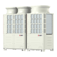
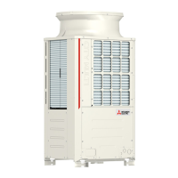
What does Error Code 5201 mean on a Mitsubishi Electric PUHY-P120YHMU-A?
- JJacob BernardSep 7, 2025
If your Mitsubishi Electric Air Conditioner is showing Error Code 5201, it indicates a high-pressure sensor fault (63HS1).

What does Error Code 5201 mean on a Mitsubishi Electric PUHY-P120YHMU-A?
If your Mitsubishi Electric Air Conditioner is showing Error Code 5201, it indicates a high-pressure sensor fault (63HS1).
What does Error Code 6608 mean on a Mitsubishi Electric PUHY-P120YHMU-A Air Conditioner?
If your Mitsubishi Electric Air Conditioner displays Error Code 6608, it indicates a no response error.
What does Error Code 6602 mean on a Mitsubishi Electric Air Conditioner?
If your Mitsubishi Electric Air Conditioner displays Error Code 6602, it indicates a transmission processor hardware error.
What does Error Code 6606 mean on a Mitsubishi Electric Air Conditioner?
If your Mitsubishi Electric Air Conditioner displays Error Code 6606, it indicates a communication error between the device and transmission processors.
What does Error Code 2600 mean on a Mitsubishi Electric PUHY-P120YHMU-A Air Conditioner?
If your Mitsubishi Electric Air Conditioner is showing Error Code 2600, it indicates water leakage.
What does Error Code 5101 mean on a Mitsubishi Electric PUHY-P120YHMU-A Air Conditioner?
If your Mitsubishi Electric Air Conditioner is showing Error Code 5101, it indicates a temperature sensor fault.
What does it mean when my Mitsubishi Electric Air Conditioner displays Error Code 4250 or 4255?
Error Codes 4250 and 4255 on your Mitsubishi Electric Air Conditioner indicate several potential issues: an instantaneous overcurrent, a short-circuited IPM/ground fault, an overcurrent error due to a short-circuited motor, or simply an overcurrent situation.
What does Error Code 4102 mean on a Mitsubishi Electric Air Conditioner?
If your Mitsubishi Electric Air Conditioner is showing Error Code 4102, it indicates an open phase.
What does Error Code 6603 mean on a Mitsubishi Electric PUHY-P120YHMU-A?
If your Mitsubishi Electric Air Conditioner displays Error Code 6603, it indicates a transmission line bus busy error.
What does Error Code 7130 mean on a Mitsubishi Electric PUHY-P120YHMU-A?
If your Mitsubishi Electric Air Conditioner displays Error Code 7130, it indicates an incompatible unit combination.
| Brand | Mitsubishi Electric |
|---|---|
| Model | PUHY-P120YHMU-A |
| Category | Air Conditioner |
| Language | English |
Essential preliminary checks and safety guidelines for servicing.
Required tools and materials for R410A unit installation and servicing.
Details on copper pipe types, radial thickness, and specifications for R410A.
Proper indoor storage and sealing of piping to prevent contamination.
Recommendations for coating flares and flanges with specific oils.
Procedures and observations for brazing copper pipes, emphasizing cleanliness.
Method for testing air tightness using nitrogen and detecting R410A leaks.
Procedures for vacuum pump usage, degree, and time for system evacuation.
Guidelines for charging R410A refrigerant in liquid phase for system safety.
Procedures for replenishing refrigerant after a leak.
Comparison of chemical properties, composition, and pressure characteristics of refrigerants.
Information on refrigerating machine oil for HFC systems and contaminant effects.
Table summarizing compatible indoor units with different outdoor units.
Guidelines for wiring work, control wiring, and maximum cable lengths for M-NET.
Instructions for setting switches and addresses for MA and M-NET controllers.
Examples of typical system connections for MA and M-NET controllers.
Sample control wiring and cautions for MA remote controller systems.
Sample control wiring and cautions for M-NET remote controller systems.
Sample control wiring and cautions for systems with both controller types.
Allowable lengths and height differences for pipes in end branching systems.
Exploded view of outdoor unit components and its refrigerant circuit diagram.
Details on the control box, internal components, and high-voltage warnings.
Diagram of the outdoor unit control board, showing connectors and components.
Comparison of MA and ME remote controllers, including address settings and wiring.
Procedures for setting groups and interlocks using the ME remote controller.
Steps for setting up LOSSNAY interlocks with indoor units using the MA remote controller.
Instructions for selecting temperature detection sources and setting modes.
Detailed wiring diagram for the PUHY-P72, P96THMU-A outdoor unit.
Wiring diagram for the transmission booster, including electronic control board connections.
Diagrams illustrating the refrigerant circuit for PUHY-P72, P96, and P120 models.
Explanation of key components like compressor, sensors, and valves in the outdoor unit.
Table detailing the functions and factory settings of outdoor unit DIP switches.
Explanation of outdoor unit control methods, startup sequences, and bypass control.
Flowcharts illustrating indoor unit operation modes and outdoor unit cooling/heating modes.
Pre-test run checks including refrigerant leaks, insulation resistance, and power supply.
Procedure for performing a test run using the MA remote controller.
Understanding refrigerant characteristics and estimating system refrigerant amounts.
Symptoms of incorrect refrigerant charge and how to adjust it.
Step-by-step procedure for adjusting refrigerant amount using self-diagnosis switches.
Common normal operational symptoms that may occur during system operation.
Tables providing reference data for standard operation under various conditions.
Comprehensive list of error codes, their definitions, and affected units.
Troubleshooting steps for common error codes displayed on the remote controller.
Methods for checking transmission line issues, including wave shape and noise analysis.
Detailed troubleshooting guides for key components like sensors and power modules.
Procedures for identifying and repairing refrigerant leaks in indoor and outdoor units.
Step-by-step instructions for safely replacing a compressor.
Guidance on interpreting LED indicators on the outdoor unit control board for error diagnosis.
Explanation of how to interpret LED indicators and display information on the service monitor.


