What does Error Code 6608 mean on a Mitsubishi Electric Air Conditioner?
- KKylie SmithSep 6, 2025
If your Mitsubishi Electric Air Conditioner displays Error Code 6608, it indicates a no response error.

What does Error Code 6608 mean on a Mitsubishi Electric Air Conditioner?
If your Mitsubishi Electric Air Conditioner displays Error Code 6608, it indicates a no response error.
What does Error Code 6602 mean on a Mitsubishi Electric PUHY-P72?
If your Mitsubishi Electric Air Conditioner displays Error Code 6602, it indicates a transmission processor hardware error.
What does Error Code 6606 mean on a Mitsubishi Electric PUHY-P72 Air Conditioner?
If your Mitsubishi Electric Air Conditioner displays Error Code 6606, it indicates a communication error between the device and transmission processors.
What does Error Code 2600 mean on a Mitsubishi Electric Air Conditioner?
If your Mitsubishi Electric Air Conditioner is showing Error Code 2600, it indicates water leakage.
What does Error Code 5101 mean on a Mitsubishi Electric Air Conditioner?
If your Mitsubishi Electric Air Conditioner is showing Error Code 5101, it indicates a temperature sensor fault.
What does Error Code 6601 mean on a Mitsubishi Electric PUHY-P72?
If your Mitsubishi Electric Air Conditioner displays Error Code 6601, it indicates a polarity setting error.
What does Error Code 4102 mean on a Mitsubishi Electric PUHY-P72 Air Conditioner?
If your Mitsubishi Electric Air Conditioner is showing Error Code 4102, it indicates an open phase.
What does Error Code 6603 mean on a Mitsubishi Electric PUHY-P72 Air Conditioner?
If your Mitsubishi Electric Air Conditioner displays Error Code 6603, it indicates a transmission line bus busy error.
What does Error Code 7130 mean on a Mitsubishi Electric PUHY-P72 Air Conditioner?
If your Mitsubishi Electric Air Conditioner displays Error Code 7130, it indicates an incompatible unit combination.
What does Error Code 7117 mean on a Mitsubishi Electric PUHY-P72?
If your Mitsubishi Electric Air Conditioner displays Error Code 7117, it indicates a model setting error.
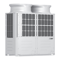
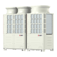
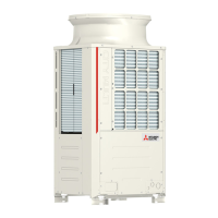
| Model | PUHY-P72 |
|---|---|
| Type | Heat Pump |
| Refrigerant | R410A |
| Outdoor Unit Noise Level | 58 dB(A) |
| Series | P Series |
General safety guidelines and precautions for installation, operation, and maintenance.
Guidelines and steps for preparing piping work, including checking refrigerant type and tools.
List of tools and materials required for R410A systems, including those to use and avoid.
Information on copper pipe materials, types, processing, and handling of refrigerants and oils.
Detailed procedures for pipe brazing, air tightness testing, and vacuum drying.
Essential safety precautions and guidelines for electrical wiring work.
Details on compatible indoor units and system capacity configurations.
Specifications for M-NET transmission lines and remote controller wiring, including length limits.
Configuration of necessary switch settings based on system setup.
Table detailing M-NET address settings for various units and controllers.
Explanation of demand control functions and how they are implemented via DIP SW6-8.
Illustrations of typical system connections for MA, ME, and combined remote controller setups.
Wiring diagrams and cautions for single refrigerant systems with MA remote controllers.
Wiring diagrams and cautions for systems using ME remote controllers with system controllers.
Wiring diagrams and cautions for systems using both MA and ME remote controllers.
Guidelines for refrigerant pipe length and size restrictions for various models.
Visual identification of outdoor unit components and their arrangement.
Diagrams illustrating the refrigerant circuits for various outdoor unit models.
Detailed explanations of the functions, specifications, and check methods for outdoor unit components.
Explanation of the functions and specifications of indoor unit components.
Layout and identification of components within the outdoor unit's control box.
Detailed breakdown of components on the Control, M-NET, INV, Fan, Noise Filter, and Connect boards.
Schematic diagrams illustrating the electrical connections for outdoor units.
Wiring diagram for the transmission booster unit.
Details on outdoor unit, indoor unit, and remote controller dipswitch functions and settings.
Overview and explanation of various control methods for the outdoor unit.
Flowcharts illustrating operational sequences for indoor and outdoor units in different modes.
Essential checks and precautions to perform before conducting a test run.
Comparison of functions and specifications between MA and ME remote controllers.
Procedures for setting up group operations and interlocks using an ME remote controller.
Guide to selecting and changing functions on the ME remote controller.
Instructions for setting up LOSSNAY interlocks using an MA remote controller.
Step-by-step guide for performing a test run using the MA remote controller.
Understanding the operating characteristics and refrigerant charge importance.
Methods for evaluating and adjusting refrigerant charge, including calculation formulas.
Description of normal operating symptoms that may occur.
Reference data for standard operating conditions of various models.
Comprehensive list of error codes and their preliminary details.
Detailed definitions and solutions for error codes in the 0-999 range.
Detailed definitions and solutions for error codes in the 1000-1999 range.
Detailed definitions and solutions for error codes in the 2000-2999 range.
Detailed definitions and solutions for error codes in the 4000-4999 range.
Detailed definitions and solutions for error codes in the 5000-5999 range.
Detailed definitions and solutions for error codes in the 6000-6999 range.
Detailed definitions and solutions for error codes in the 7000-7999 range.
Troubleshooting steps for common issues with MA remote controllers.
Troubleshooting steps for common issues with ME remote controllers.
Diagnosis and solutions for issues related to refrigerant control and capacity.
Methods for checking transmission waveforms and identifying electrical noise issues.
Configuration and troubleshooting for high and low-pressure sensors.
Troubleshooting procedures for various solenoid valves.
Diagnosis and solutions for issues related to outdoor unit fans and their control.
Troubleshooting steps for linear expansion valves (LEV) in indoor and outdoor units.
Comprehensive troubleshooting guide for inverter-related issues specific to TLMU models.
Comprehensive troubleshooting guide for inverter-related issues specific to YLMU models.
Explanation of control power supply function blocks for TLMU models.
Explanation of control power supply function blocks for YLMU models.
Procedures and precautions for detecting and repairing refrigerant leaks.
Step-by-step instructions for removing and replacing the compressor.
Instructions for safely replacing the heat exchanger, considering material properties.
Guide to interpreting LED status indicators on the outdoor unit circuit board for troubleshooting.
Overview of LED status indicators and how to read them.
Explanation on how to interpret numerical and flag displays from LEDs.
Information displayed on the monitor screen during initial settings.
Comprehensive table mapping SW4 settings to LED status and display information.


