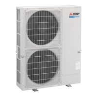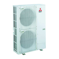
Do you have a question about the Mitsubishi Electric PUHZ-P200YKA.UK and is the answer not in the manual?
| Brand | Mitsubishi Electric |
|---|---|
| Model | PUHZ-P200YKA.UK |
| Category | Air Conditioner |
| Language | English |
General safety guidelines before accessing terminals.
Cautions for units utilizing refrigerant R410A.
Flowchart and precautions for reusing R22 refrigerant pipes.
List of exclusive service tools for R410A refrigerant.
Cautions for refrigerant piping work with R410A.
Pre-charged refrigerant supplied for piping length at shipment.
Refilling refrigerant charge amounts for PUHZ-P200/250 models.
Adjusting refrigerant amount based on pipe length for PUHZ-P200/250.
Technical data for the compressor model ANB52FRNMT.
Noise criterion curves for PUHZ-P200YKA and PUHZ-P250YKA.
Standard operation data for representative matching indoor units.
Power wiring specifications for outdoor units.
Electrical wiring diagrams for synchronized twin and triple systems.
Available connection patterns for separate indoor/outdoor unit power supplies.
Wiring specifications for indoor-outdoor connecting cables.
Method for wiring M-NET communication cables.
Procedure for setting M-NET address on the outdoor unit.
Procedure for setting refrigerant address for multiple grouping systems.
Rules for setting M-NET and refrigerant addresses in multiple grouping systems.
Procedure for collecting refrigerant before relocation or disposal.
Steps for starting and finishing a test run operation.
Summary of check codes and actions for recurring and non-recurring troubles.
Points to check before and during test run.
Procedure for test run using a wired remote controller.
Displays error status, stops operation, and consults dealer.
Viewing error information and history from the main menu.
Checking and deleting error history records.
Procedure for test run using a wireless remote controller.
Steps to initiate self-diagnosis for troubleshooting.
Performing self-diagnosis using the wired remote controller.
Procedure to reset error history after troubleshooting.
Function to diagnose remote controller issues.
Performing self-diagnosis using a wireless remote controller.
List of errors detected by the indoor unit with check codes.
List of errors detected by outdoor unit with check codes.
Table detailing actions for detected abnormalities when power is on.
Table detailing actions for detected abnormalities during communication.
Details on abnormalities detected during unit operation.
Details on abnormalities related to thermistors and power modules.
Details on abnormalities related to power signals and sensors.
Details on abnormalities related to overheat, compressor, and low pressure.
Detailed tables covering error codes, symptoms, and actions.
Details on M-NET communication errors and their causes.
Further details on M-NET communication errors and troubleshooting.
More M-NET communication error scenarios and their resolutions.
Troubleshooting common operational problems and symptoms.
Troubleshooting steps when the remote controller display is blank.
Troubleshooting when "PLEASE WAIT" persists on the remote controller.
Troubleshooting when operation display appears briefly then turns off.
Troubleshooting when unit does not start despite remote controller input.
Troubleshooting when unit doesn't start after beep sound.
Troubleshooting cooling capacity issues when remote display is normal.
Troubleshooting heating capacity issues when remote display is normal.
Diagnosis flow for persistent "PLEASE WAIT" display on the remote controller.
Diagnosis flow for no display on the remote controller.
Continued diagnosis flow for no remote controller display.
Final diagnosis flow for no remote controller display.
Table and charts showing thermistor resistance values at different temperatures.
Procedure for checking the DC fan motor and related components.
Summary of linear expansion valve operation and pulse signals.
Explanation of linear expansion valve operation based on pulse numbers.
Instructions for attaching and detaching the linear expansion valve coil.
Conditions and procedure for emergency operation.
Items and cautions to check before performing emergency operation.
Step-by-step procedure for initiating emergency operation.
Steps to safely release from emergency operation mode.
Operation data values used during emergency operation.
Diagram showing test points on the outdoor controller circuit board.
Diagram showing connections on the outdoor noise filter circuit board.
Diagram showing test points and components on the outdoor power circuit board.
Explanation of the functions of DIP switches and push switches.
Continued explanation of DIP switch functions like model select and defrost.
Explanation of functions for connectors like CN31 and CNDM.
Details on special functions like low-level sound priority and on-demand control.
Normal operating status indicators for outdoor controller board LEDs.
Abnormal condition indicators based on LED blinking and check codes.
Detailed error codes and their corresponding abnormalities and inspection methods.
Explanation of LED1 display for operation mode and relay output.
How postponement codes are displayed when the compressor stops.
Indicators for inspection codes when the compressor stops due to protection devices.
SW2 settings for displaying pipe temperature, fan step, and compressor data.
SW2 settings for temperature, current, error history, and thermostat ON time.
SW2 settings for capacity, setting information, and indoor pipe temperatures.
SW2 settings for temperatures, discharge superheat, input current, and error history.
SW2 settings for capacity save, error postponement, and thermistor display.
SW2 settings for pipe temperatures, discharge superheat, sub-cool, and thermo-ON time.
SW2 settings for compressor operating frequency, fan step, and indoor room temperature.
Setting unit functions using the remote controller.
Available functions based on unit number and system type.
Procedure for selecting functions via wired remote controller.
Steps for setting indoor unit refrigerant addresses and unit numbers.
Procedure for selecting functions via wireless remote controller.
Details on function selection using PAR-30MAA/PAR-31MAA remote controllers.
Menu structure for navigating functions on the remote controller.
List of main menu items and their setting details.
Steps to confirm operation data and error history via remote controller.
Detailed instructions for monitoring data with PAR-30MAA/PAR-31MAA.
List of request codes and their corresponding descriptions and units.
Continuation of request code list with more details.
Further continuation of the request code list.
Final part of the request code list.
Detailed contents for specific request codes like operation and control states.
Details on fan control states based on request code 53.
Details on actuator output states based on request code 54.
Details on error content U9 based on request code 55.
Details on contact demand capacity based on request code 61.
Details on external input states based on request code 62.
Details on outdoor unit capacity settings based on request code 70.
Details on outdoor unit setting information based on request code 71.
Details on indoor unit model settings based on request code 162.
Details on indoor unit capacity settings based on request code 163.
Details on wireless pair settings based on request code 165.
Performing smooth maintenance to check unit data.
Instructions for smooth maintenance using PAR-30MAA/PAR-31MAA.
Explanation of refrigerant address settings for single and multi-system.
Steps to remove the service and top panels.
Steps to remove the fan motor assembly.
Steps to remove the electrical parts box.
Steps for disassembling the electrical parts box components.
Steps to remove the 2-phase pipe thermistor (TH6).
Steps to remove the ambient thermistor (TH7).
Steps to remove the liquid and comp. surface thermistors.
Steps to remove the 4-way valve coil, LEV coil, and high pressure switch.
Steps to remove the 4-way valve, LEV, and high pressure switch.
Steps to remove the compressor.
Steps to remove the power receiver.


 Loading...