4 - 3
4 INSTALLATION AND WIRING
4.1.2 Instructions for installation of the base unit
Install the Motion controller module to a panel, etc. , considering enough about
operability, maintainability and environmental resistance.
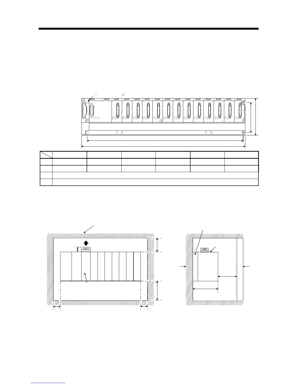
(1) Fitting dimensions
Fitting dimensions of each base unit are as follows:
I/11
0358
I/10I/09I/08I/07I/06I/05I/04I/03I/02I/01I/00
CPU
POWER
5V
56
F6
Ws
W
Hs
H
4 fixing screw (M4 14)
Q35B Q38B Q312B Q65B Q68B Q612B
W 245 (9.65) 328 (12.91) 439 (17.28) 245 (9.65) 328 (12.91) 439 (17.28)
Ws 224.5 (8.84) 308 (12.13) 419 (16.50) 222.5 (8.76) 306 (12.05) 417 (16.42)
H 98 (3.86)
Hs 80 (3.15)
[Unit: mm (inch)]
(2) Motion controller installation position
For enhanced ventilation and ease of module replacement, leave the following
space between the module top/bottom and structure/parts.
20mm
(0.79inch)
The wind blows lies
Door
Control
panel
30mm
(Note-2)
(1.18inch)
or more
100mm
(3.94inch)
or more
5mm
(0.20inch)
or more
5mm
(Note-1)
(0.20inch)
or more
Motion
controller
100mm
(3.94inch)
or more
Top of panel or wiring duct
Motion CPU module
98mm
(Note-3)
(3.86inch)
Base unit
(Note-1) : When the extension cable is connected without removing the adjacent module: 20mm (0.79 inch) or more.
(Note-2) : Q173CPU/Q172CPU : 50mm (1.97 inch) or more
Q173CPUN(-T)/Q172CPUN(-T)(Height of a wiring duct is 50mm (1.97 inch) or more) :
40mm (1.57 inch) or more
(Note-3) : Q173CPUN(-T)/Q172CPUN(-T) : 123mm (4.84 inch)
 Loading...


