LED.
.
established.
If it fails to repeat, connect the Mente PC, and continue to collect data.
YES
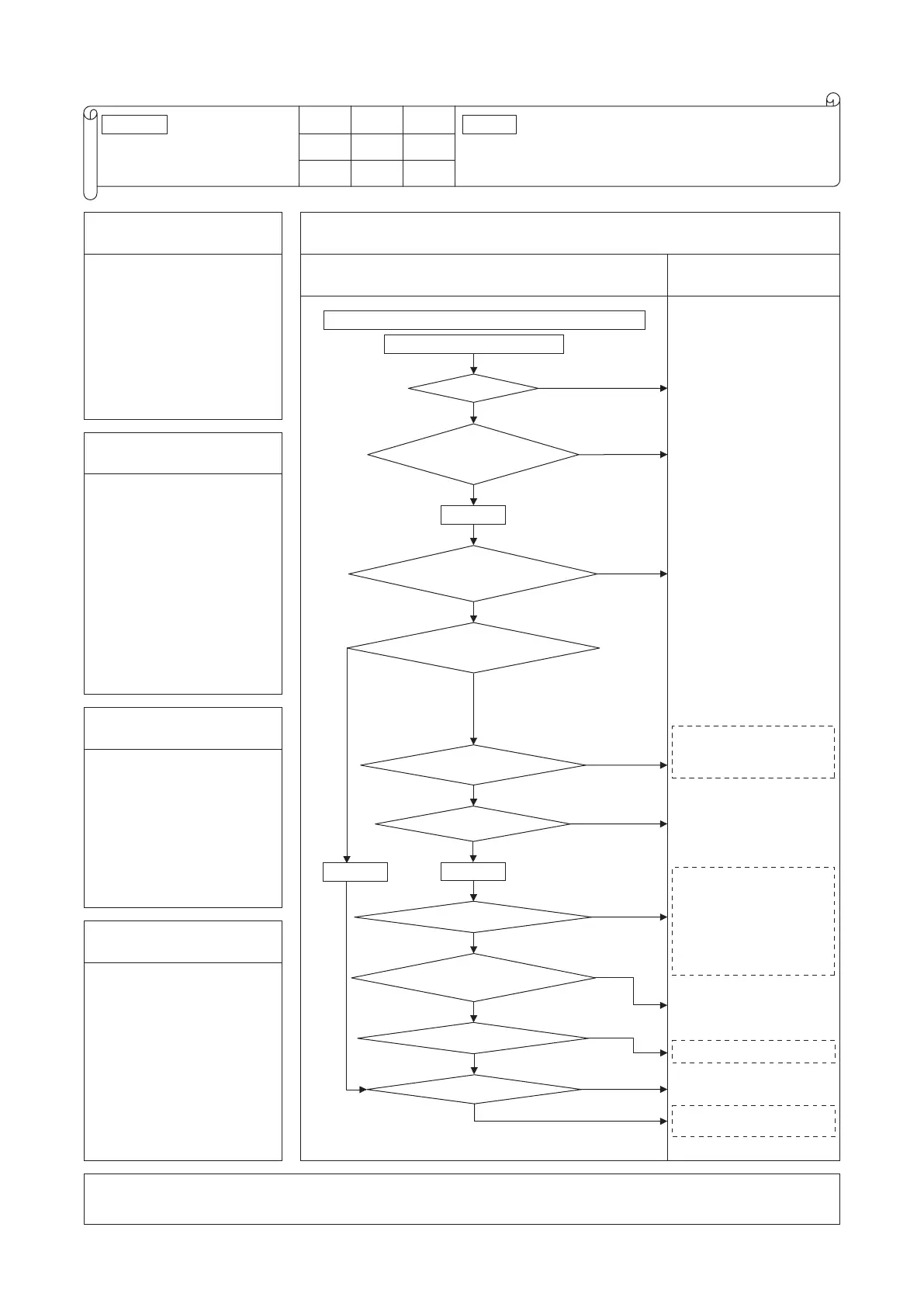
Reset the power source, and restart.
Does it repeat?
Does 52X turn ON?
NO
Turn power OFF. Check for
proper connection of harnesses and connectors
between inverter and control
PCBs.
Is DC 12V power source
detected on control PCB? (*1)
Are harness and connectors
connected properly between inverter PCB
and diode modules?
Wait and see.
Check, record operating condition.
Check under operating
condition 30 minutes
earlier than the error, as
much as possible.
Replace control PCB.
NO
NO
NO
NO
NO
NO
Is there short-circuit or broken wire between diode modules?
YES
NO
NO
YES
Is green or red LED flashing
or lighting on inverter PCB?
Save data for 30 minutes before stopping in Mente PC.
Power ON
Is surge suppressor resistor coil broken?
Power OFF
Power OFF
YES
YES
YES
NO
YES
YES
YES
YES
Disconnect harness connected to
resistor, and check resistance
between terminals. If wires are
broken, replace resistor. If wires are
broken, check also harness between
diode modules and inverter. If
resistor is blown again after
replacing it, replace diode modules.
Check if harness wires are
broken. Check if connectors are
connected securely. Correct if
there is any problem.
When it fails to turn ON even if it is
turned ON from the maintenance PC,
check voltage at connector (*2) on
control PCB. If AC 220/240V is
detected, replace 52X.
If it shows 0V, replace control PCB.
Check after confirming that
52X is turned ON.
Replace inverter PCB.
Check after confirming that
52X is turned ON.
Check for broken wires on harness,
disconnected connectors.
Correct if there is any problem.
Replace diode modules.
Correct setting of switches
on inverter PCB.
Replace inverter PCB.
If error still persists, replace control PCB.
Are switches set properly on inverter PCB?
Is DC 280V detected
between P-N of power transistor?
 Loading...