t°
t°
t°
t°
t°
t°
t°
CNI1
+
-
+
-
+
-
-
60
-
'14 • KX-SM-221
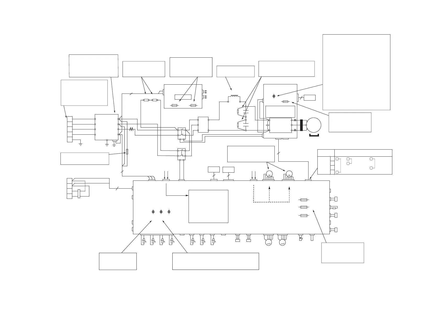
(d) Outdoor unit control failure diagnosis circuit diagram
※
52X2
5A
52X1
TB2
TB1
PCB3
N/F PCB
PCB4
POWER PCB
CNI1CNFAN2CNFAN1
CNA2
PCB4
CNA4
PCB4
CNA3
CNECNVCNM1CNA1
CNW
CNQ1CNEEV2CNEEV1
EEVH EEVSC
CNL2
PSL
CNP1CNF2CNU1CNTH
CNX1
CNX2
CNZ
RESERVE
CNZ1
CNR1
CH1
SV1
SV6
20SCNN1
CNN3
CNN8
PCB1
CONTROL PCB
SW POWER SOURCE
13V : FOR ACTUATOR DRIVE
15V : FOR FAN MOTOR
5V : FOR CONTRL
MICROCOMPUTER
DC280V
POWER SOURCE
+
+
U
V
W
U
V
P
N
W
MS
3
~
CM
L1,1
L1,2
R1,2 R2,1 R2,2
CNW1
(L1,N)
PCB1 CNA2
PCB1 CNA1
CT1
CNE
CNA
CNR
CNI2 CNI3
6
4
RAM
CHECKER
Tho-STho-A Tho-D1 Tho-R1 Tho-C1 Tho-H
63H
L1
L2
L3
N
E
A1
B1
A2
L1i
L2i
L3i
Ni
CN1E
L1o
L2o
L3o
No
PCB2
INVERTER PCB
IPM
CL1A 25A
1200V
SW POWER SOURCE
15V(×3) : FOR IPM P-SIDE
15V : FOR IPM N-SIDE
5V : FOR INVERTER
MICROCOMPUTER
MM
67
RAM
CHECKER
PC
RESERVE
R4
C2
R3
C1
M
M
1
3
5 6
4
2
1
3
5 6
4
2
DM
AC2
~
AC1
~
AC3
~
+
-
R1,1
R1 R2
※
Power source check:
Measure the power source
L1,L2,L3
(It is normal if it is
AC380-415V)
FDC224KXZPE1,280KXZPE1
●
Outdoor unit check points
Check items with the
※ mark when the power is ON.
Noise filter check:
There should be continuity.
There should be no shorts
between phases.
Resistance check:
Resistance is measured
(15Ω)
DC Reactor contiuity
check:55mΩ or less
Capacitor check:
Check for anomaly in appearance
such as damage, swelling, etc.
When the outdoor unit fan
motor is anomalous.
(Refer to page 107, 108)
LED1
(Yellow)
F1 (250V, 3.15A)
Fuse check:There should
be continuity.
If it is faulty, replace the
inverter board.
LED1 (Yellow) Check
1 - time flash : Current cut (IPM)
2 - times flash: Power transister
overheat
3 - times flash: Anomalous compressor
by less of synchronism
4 - times flash: Compressor startup
failure
8 - times flash: Anomalous circuit
of prevention of
decrease magnetic force
9 - times flash: Current cut
(Operate the circuit of
protection of decrease
magnetic force)
LED2
(Green)
LED1
(Red)
LED1 (Red) check:
1-5 time flash
(Refer to item 2.3)
3
2
L1
B2
CNSL1,2
CN17
CNF1
Tho-SC
CNB2
RESERVE
CNL1
PSH
RESERVE
RESERVE
CNN2
RESERVE
RESERVE
CNS1
EXTERNAL
OPERATION
FMO1 FMO2
CNA4
CNA3
2
F1 (250V, 2.5A)
F3 (250V, 0.4A)
Fuse check:There should
be continuity.
If it is faulty, replace the
control board.
Fuse check: There should
be continuity.
If it is faulty, replace the
fuse.
F1 (250V, 6.3A) F2 (250V, 4A)
Fuse check:
There should be continuity
LED3
(Green)
LED2 (Green) check:
Flash the LED : Microcomputer normally operate
Not flash the LED : Check the connector of “CNI1”
F2 (250V, 0.4A)
Conector Voltage
1
2
3
4
DC4 - 5V
DC3 - 12V
DC8 - 12V
※
 Loading...