-
291
-
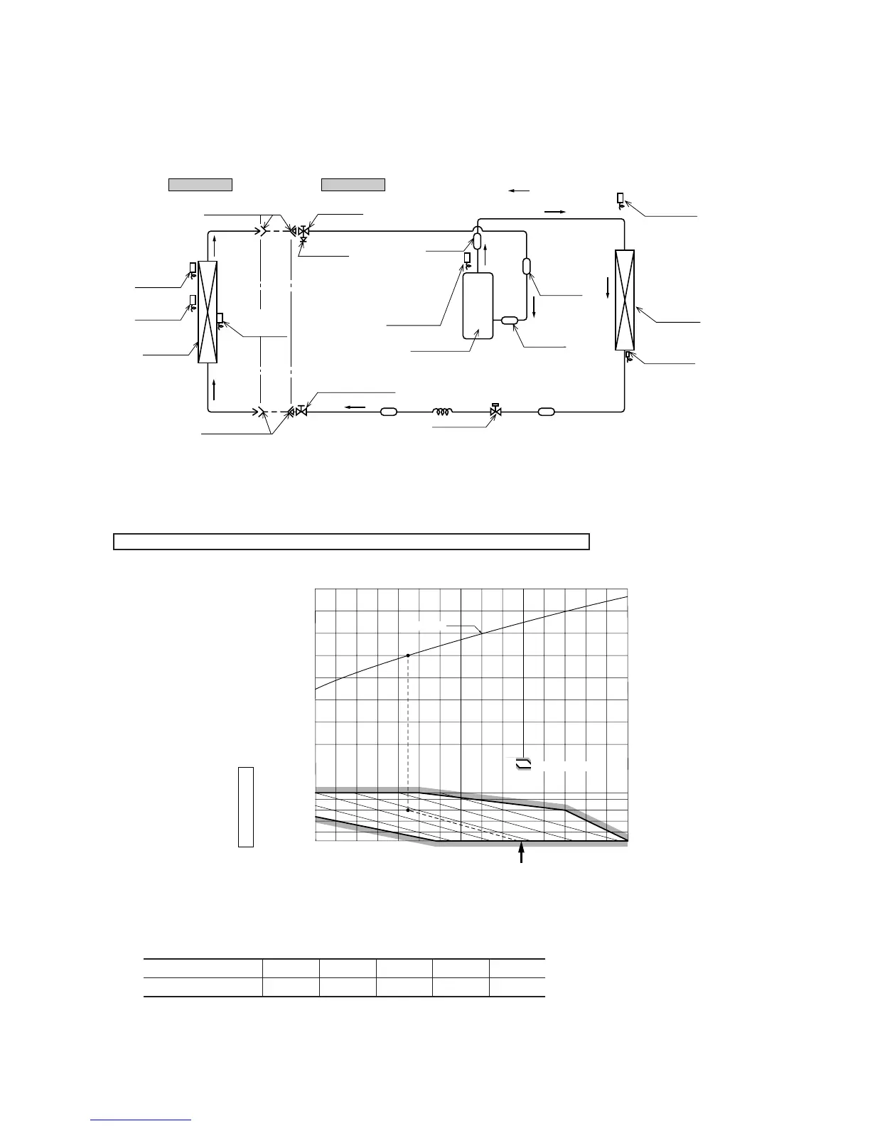
Outdoor unitIndoor unit
Room temp.
sensor
Humidity
sensor
Heat
exchanger
Flare connecting
Heat
exchanger
sensor
Piping
(Liquid)
ø
6.35
Piping
(Gas)
63:
ø
12.7
71:
ø
15.88
Check joint
Service valve (Liquid)
Flare connecting
Discharge pipe
temp. sensor
Cooling cycle
Muffler
Outdoor air
temp. sensor
Heat
exchanger
Heat exchanger
sensor
Compressor
Capillary tube
Strainer
Strainer
(71 model only)
accumulator
Sub
Accumulator
Service valve
(Gas)
Electronic
expansion valve
Models SRK63CE-S1, 71CE-S1
( )
(4) Piping system
(5) Selection chart
Correct the cooling capacity in accordance with the conditions as follows. The net cooling capacity can be obtained in the following
way.
Net capacity = Capacity shown on specification ✕ Correction factors as follows.
(a) Coefficient of cooling capacity in relation to temperatures
(2) Correction of cooling capacity in relation to one way length of refrigerant piping
It is necessary to correct the cooling capacity in relation to the one way piping length between the indoor and outdoor units.
16 18 20 22 24
ISO-T1 Standard ConditionIndoor air W.B. temperature ˚C W.B.
Applicable range
0.6
0.7
0.8
0.9
1.0
1.1
1.2
1.3
Cooling
Coefficient of cooling &
Heating capacity in
relation to temperature
Cooling operation
Outdoor air D.B.
temperature
˚C D.B.
21
25
30
35
40
43
Piping length [m]
Cooling
7
1.0
10
0.99
15
0.975
20
0.965
25
0.95
 Loading...