..
..
.
6.
LOADING AND INSTALLATION
/MELSEC=A
(2)
Wiring of
I/O
equipment
(a)
Applicable size of wire to the terminal block connector is
0.3 (18)
to
2
mm2
(14
AWG). However,
it
is recommended
to use wires of
0.75
mm2
(18
AWG) for convenience.
(b) Separate the input and output lines.
(c)
I/O
signal wires must be at least
100
mm
(3.94
in)
away
from high-voltage and large-current main circuit wires.
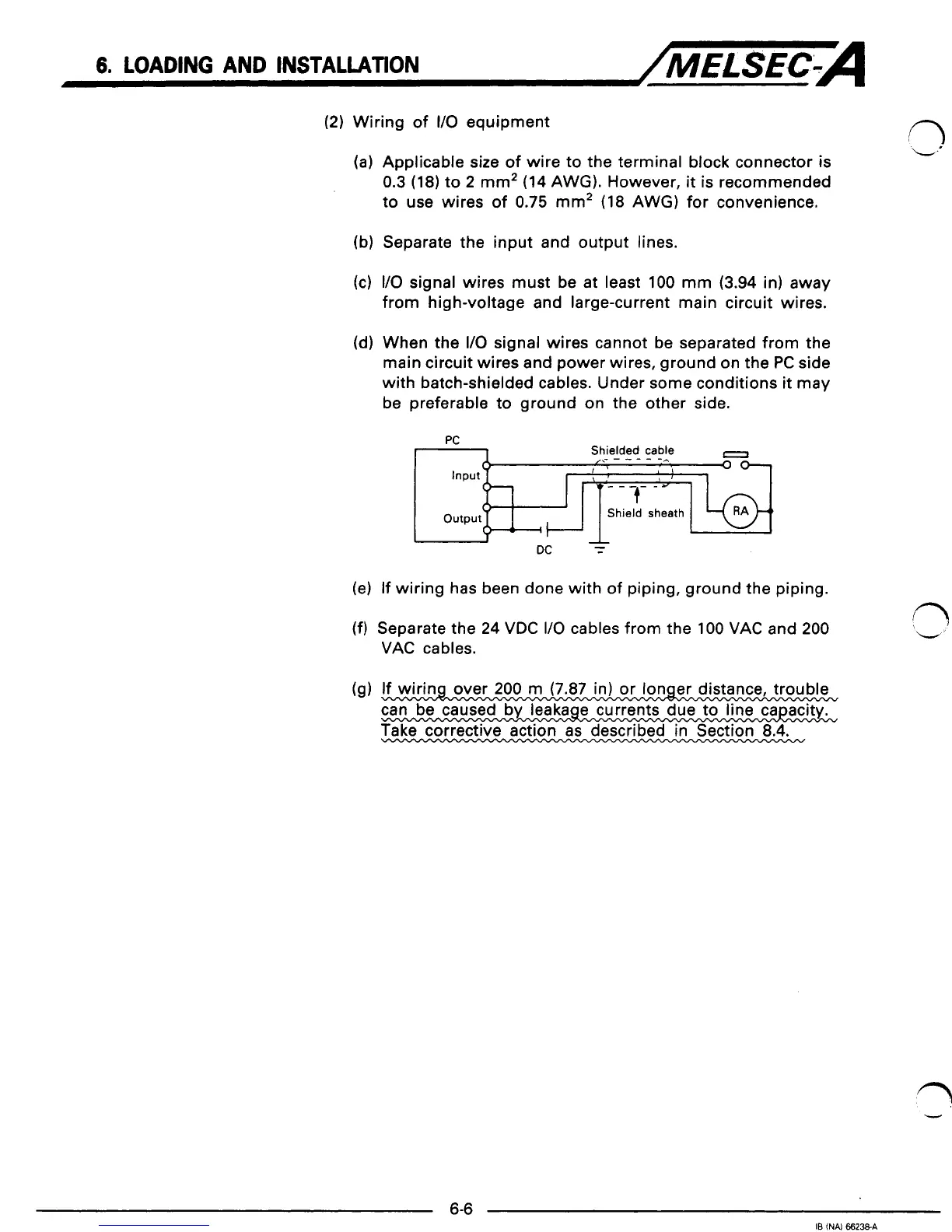
(d)
When the
I/O
signal wires cannot be separated from the
main circuit wires and power wires, ground on the
PC
side
with batch-shielded cables. Under some conditions
it
may
be preferable to ground on the other side.
PC
Shielded cable
,x-----
-e
,
0
I'
I
0-
Shield sheath
I
A
DC
-
-
(e) If wiring has been done with of piping, ground the piping.
(f)
Separate the
24
VDC
I/O
cables from the
100
VAC and
200
VAC cables.
1
Take corrective action as described in Section
8.4.
-
i
U
1
1
i
1
4
1
1
J
1
 Loading...


