7.
TEST
RUN
/MELSEC-A
7.
TEST
RUN
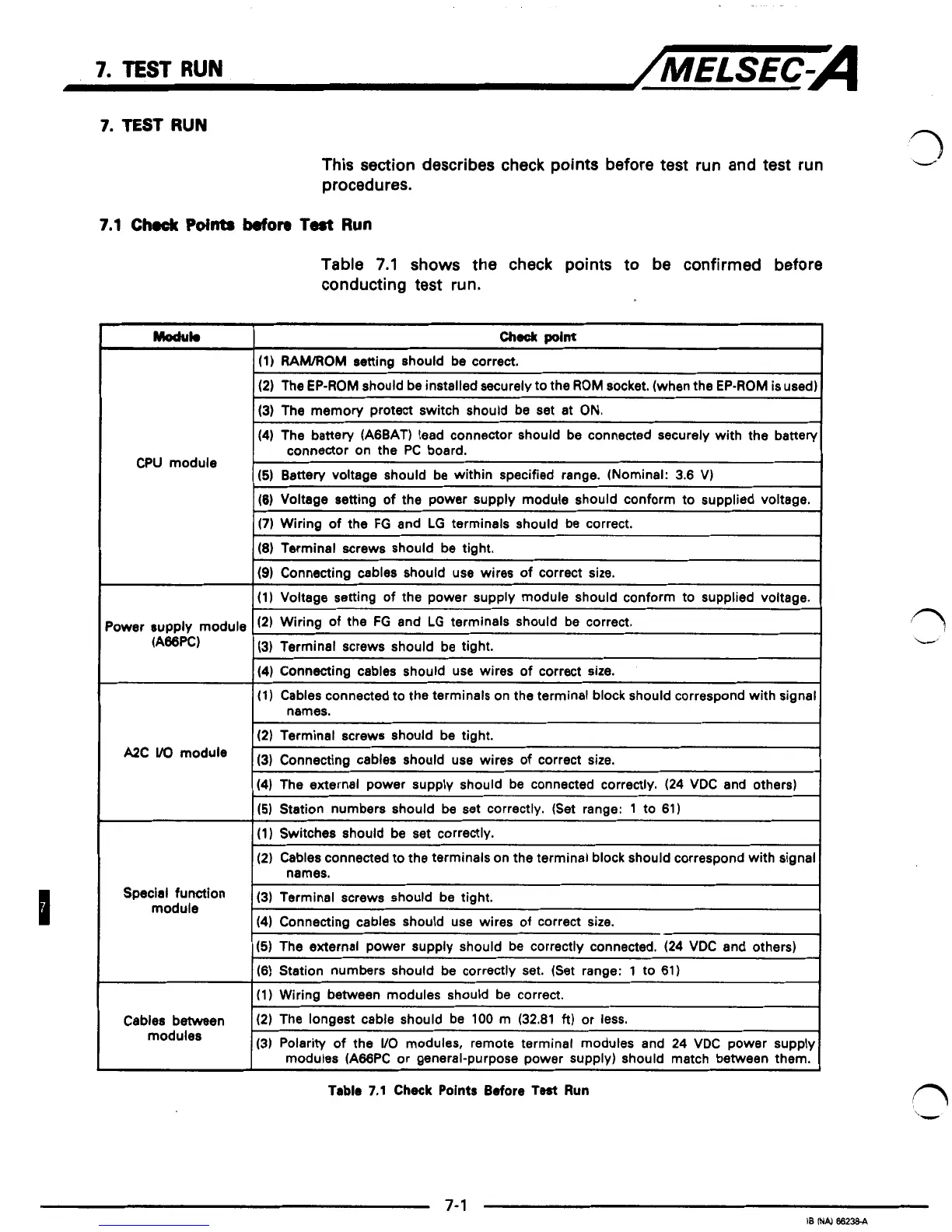
This section describes check points before test run and test run
procedures.
7.1
Check
Points
Wore
Test
Run
Table
7.1
shows the check points to be confirmed before
conducting test run.
Moduk
check
point
(1)
RAMOM
setting should be correct.
(2)
The EP-ROM should be installed securely to the
ROM
socket. (when the EP-ROM is used)
(3)
The memory protect switch should be set at ON.
(4)
The battery (A6BAT) lead connector should be connected securely with the battery
(5)
Battery voltage should be within specified range. (Nominal: 3.6 V)
CPU module
connector on the PC board.
'ower supply module
(A66PC)
(6)
Voltage setting of the power supply module should conform to supplied voltage.
(7)
Wiring
of
the
FG
and
LG
terminals should be correct.
(8)
Terminal screws should be tight.
(9)
Connecting cables should use wires
of
correct size.
(1) Voltage setting of the power supply module should conform to supplied voltage.
(2)
Wiring of the
FG
and
LG
terminals should be correct.
(3)
Terminal screws should be tiaht.
(4)
Connecting cables should use wires of correct size.
(1)
Cables connected to the terminals on the terminal block should correspond with signal
(2)
Terminal screws should be tight.
names.
A2c
(3)
Connecting cables should use wires of correct size.
(4)
The external power supply should be connected correctly.
(24
VDC and others)
(5)
Station numbers should be set correctly. (Set range:
1
to 61)
(1) Switches should
be
set correctly.
(2)
Cables connected to the terminals on the terminal block should correspond with signal
names.
Special
function
(3)
Terminal screws should be tight.
module
(4)
Connecting cables should use wires
of
correct size.
(5)
The external power supply should be correctly connected.
(24
VDC and others)
(6)
Station numbers should be correctly set. (Set range:
1
to
61)
(1)
Wiring between modules should be correct.
Cables between
(2)
The longest cable should be 100 m
(32.81
ft)
or less.
modules
(3)
Polarity of the
WO
modules, remote terminal modules and
24
VDC power supply
modules (A66PC or general-purpose power supply) should match between them.
Table
7.1
Check
Points
Before
Test
Run
1
1
3
1
1
1
3
3
3
1
3
f7,
7-
1
18
IN4
6623e-A
 Loading...


