APPENDICES
/MELSEC=A
-
Lmk
-
wo2l
D9034
to
gtod
Data
Erplm.tion
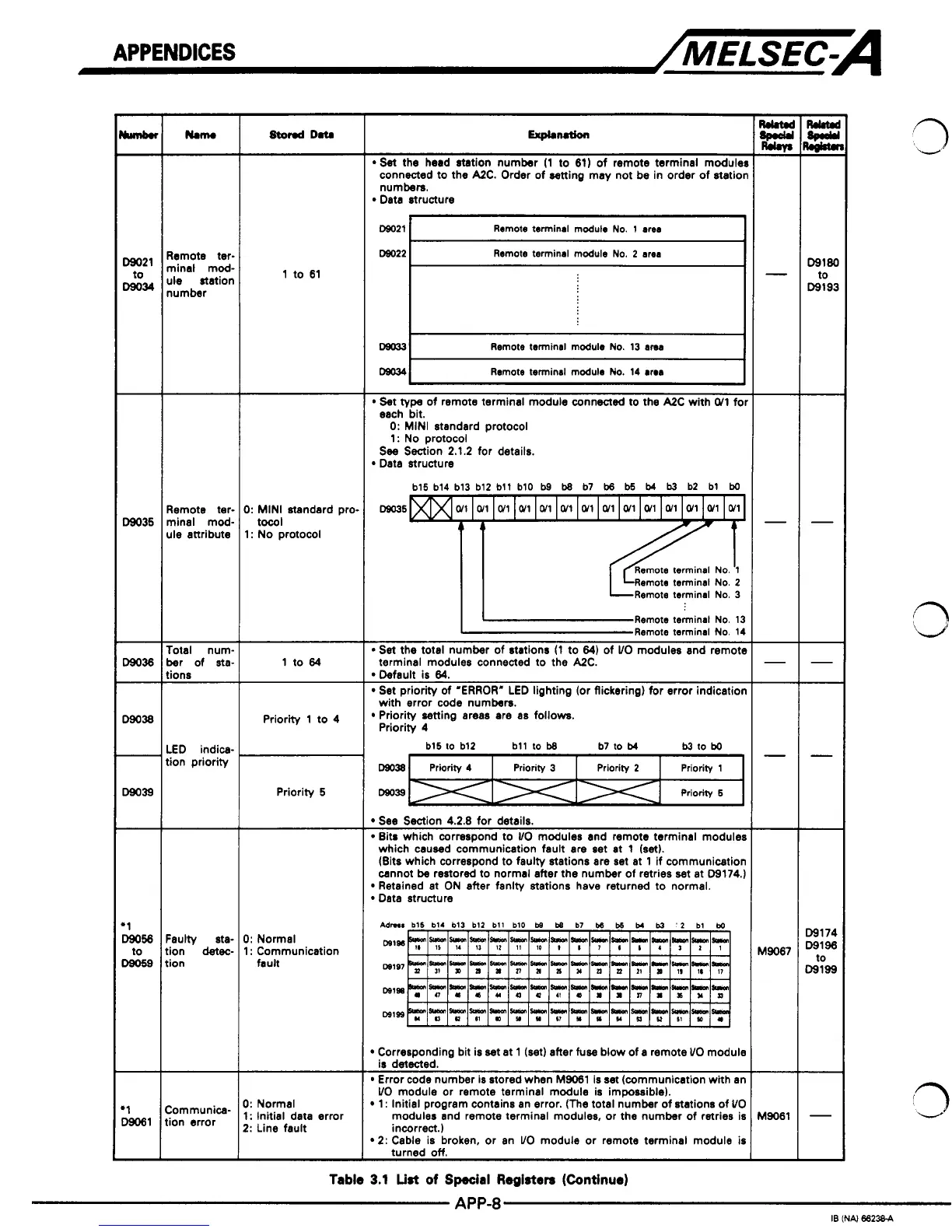
*Set
the head station number
(1
to
61)
of remote terminal moduler
connected to the A2C. Order of aetting may not be in order of statior
numbers.
Data structure
Remote terminal module
No.
1 area
I
Remote terminal module
No.
2
area
I
Remote tev
minal mod.
ule station
number
1
to
61
D8Q33
Remote terminal module
No.
13 area
Remote terminal module
No.
14 area
I
Set type of remote terminal module connected to the A2C with
W1
fol
~~
each bit.
0:
MINI standard protocol
1:
No protocol
See
Section
2.1.2
for details.
Data structure
b15 b14 b13 bl2 btl b10
b9
b8
b7
b6
b5
t4
b3
b2 bt
bo
m5
Remote terminal
No.
13
Remote terminal
No.
14
Set the total number of stations
(1
to
64)
of
VO
modules and remote
terminal modules connected to the A2C.
Default is
64.
Set priority of "ERROR" LED lighting (or flickering) for error indication
Priority setting areas are
as
follows.
with error code numbers.
Priority
4
bt5 to bl2 btt to
b8
b7
to
b4
b3
IO
bo
CIS038
Priority 4 Priority 1 Priority
2
Priority
3
3:
MINI standard pro.
1:
No protocol
tow1
Remote ter.
ule attribute
mind mod.
Total num.
ber
of
sta.
tions
LED indica-
tion priority
1
to
64
Priority
1
to
4
Prioritv
5
Dm39
Priority
5
See
Section
4.2.8
for details.
Bits which correspond to
VO
modules and remote terminal modules
which caused communication fault are set at
1
(set).
cannot be restored to normal after the number of retries set at
09174.)
(Bits which correspond to faulty stations are set at
1
if communication
Retained st ON after fanlty stations have returned to normal.
Data structure
pdrna
b15 b14 bl3
bl2
bll
b10
bs
t4
b7
W
bs
M
b3
'2
bl
bQ
mlm
W107
Wlm
Wlgo
D9174
D9196
D9199
to
-
I:
Normal
I:
Communication
fault
Faulty
st*
tion
detec-
tion
Communica-
tion error
bl9067
-
49061
-
Corresponding bit is set at
1
(set) after fuse blow of a remote
UO
module
Error code number is stored when
M9061
is set (communication with an
1
:
Initial program contains an error.
(The
total number
of
stations of
VO
modules and remote terminal modules, or the number of retries is
2:
Cable is broken. or an
UO
module or remote terminal module
is
incorrect.)
is detected.
VO
module or remote terminal module is impossible).
I:
Normal
I:
Initial data error
2:
Line fault
Table
3.1
List
of
Spacial
Registen
(Continue)
 Loading...


