2.
SYSTEM
CONFIGURATION
-/MELSEC-A
2.2
Notes
on
System Construction
(1) Connection
of
remote
I/O
modules and remote terminal
modules
A maximum
of
64
stations
of
remote
I/O
modules and remote
terminal modules can be connected to the A2C.
Also, the MINI-S3 link disclose devices can be connected. (See
Section 2.3.)
(2) Applicable remote terminal modules
A
maximum
of
14 remote terminal modules among those
mentioned below can be connected to the A2C. However,
when only the AJ35PTF-R2 RS-232C interface module is used,
up to
7
modules can be connected.
a)
A68ADC ND conversion module
b) AD61C high speed counter module
c) AJ35PTF-R2 RS-232C interface module (no-protocol mode
only)
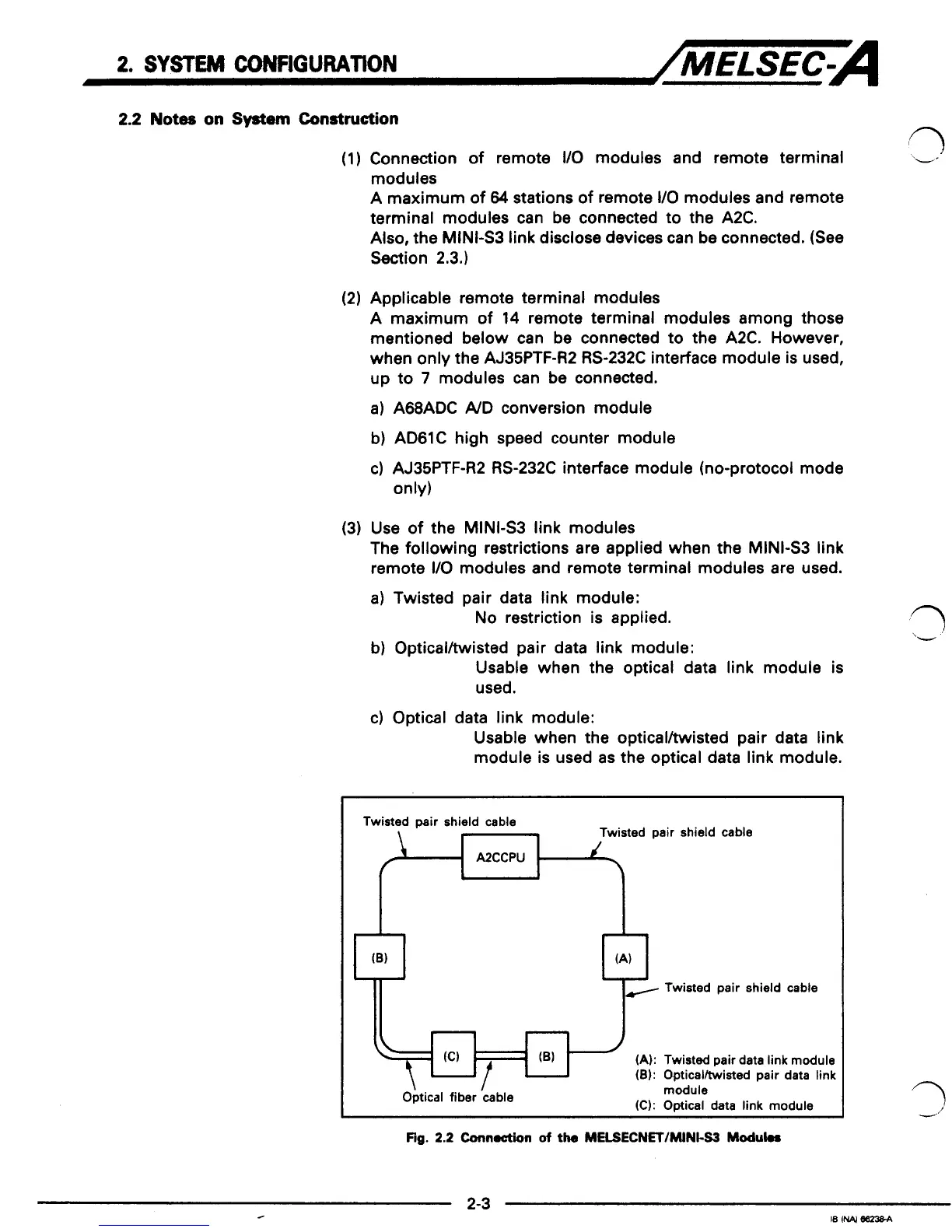
(3) Use
of
the MINI43 link modules
The following restrictions are applied when the MINI-S3 link
remote
I/O
modules and remote terminal modules are used.
a) Twisted pair data link module:
No
restriction is applied.
b) Opticalltwisted pair data link module:
Usable when the optical data link module is
used.
c) Optical data link module:
Usable when the opticalhisted pair data link
module is used as the optical data link module.
Twisted pair shield cable
Twisted pair shield
cable
A2CCPU
(A):
Twisted pair data link module
(8):
Opticalltwisted pair data
link
\
I
Optical fiber
cable
module
(C):
Optical data link module
Fig.
2.2
Cunnoction
of
the
MELSECNET/MINt-S3
Moduk.
 Loading...


