α
Simple Application Controller
Installation 3
11
ENG
3. Installation
3.1 DIN RAIL Mounting
Units can be snap mounted to 35mm DIN rail (DIN
EN 50022). To release pull the spring loaded clips
away from the rail and slide the unit off and up.
3.2 Termination at Screw Terminals
Cables terminating at a screw terminal should be
fitted with insulated crimp terminals.
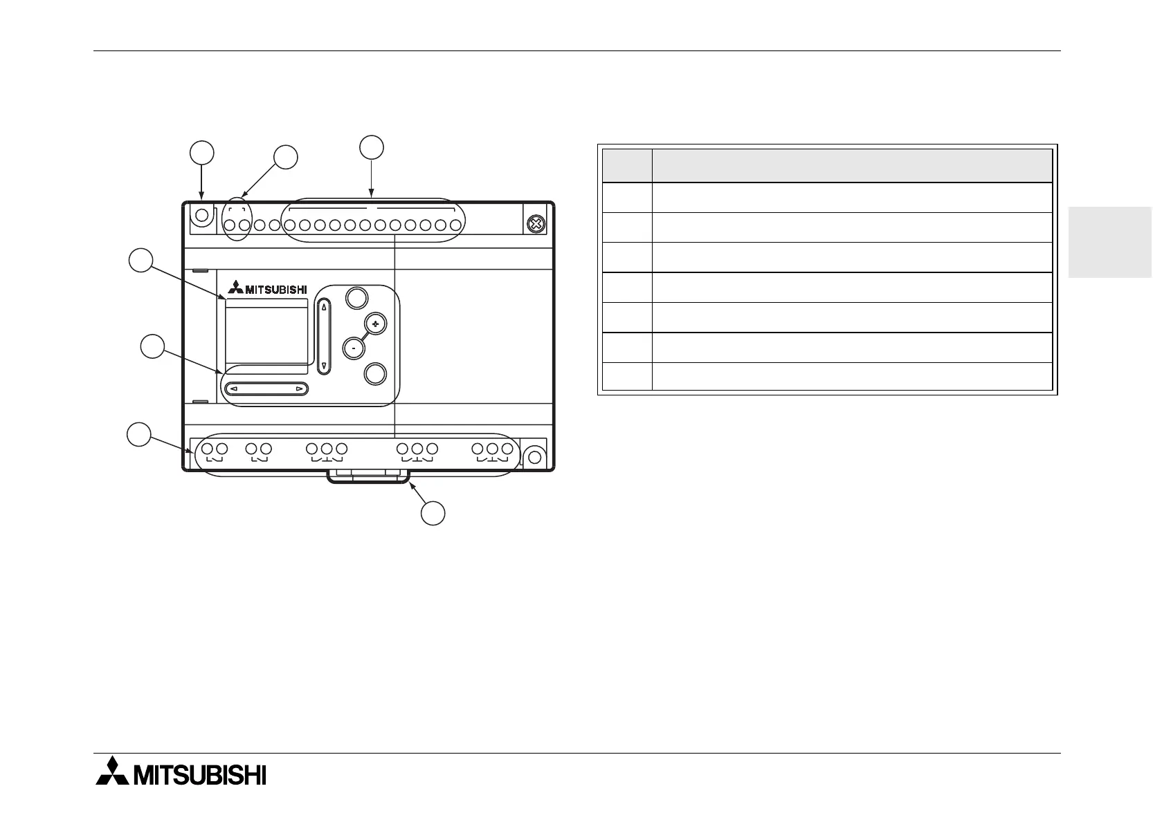
Table 3.1: Front Panel Layout
Ref. Item Description
1 DIN-RAIL Mounting clips
2 Mounting hole, Dia. 4.2 mm
3Power Terminals
4 Input Terminals
5 Liquid Crystal Display
6 Operation keys
7 Output Terminals
AC 100-240V
POWER
AC INPUT
AL-20MR-A
OK
ESC
RELAY OUTPUT
OUT
1
OUT
2
OUT
5
OUT
3
OUT
4
OUT
6
OUT
8
OUT
7
1 2 3 4 5 6 7 8 9 10 11 12
IN
LN
~
4
3
2
5
6
7
1
 Loading...


