α
2 Simple Application Controllers
Installation 3
ENG-16
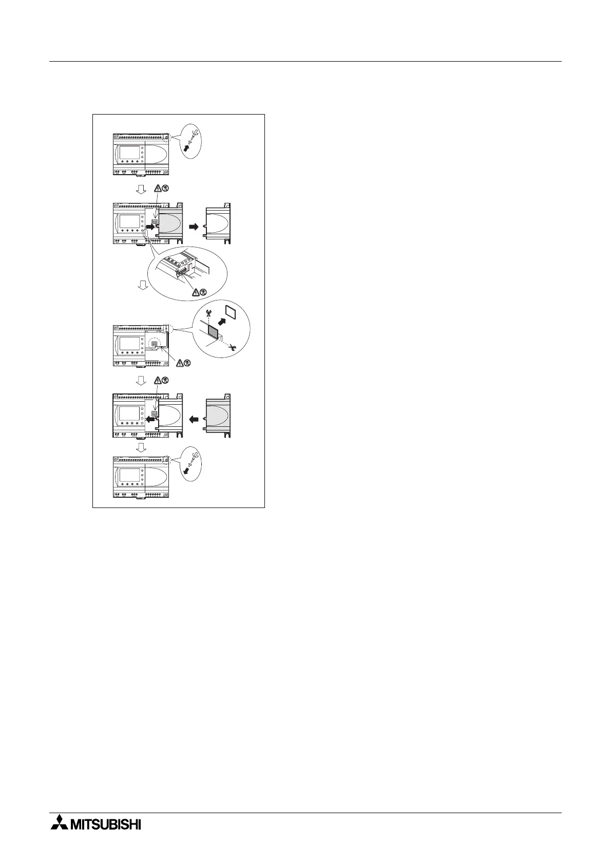
Figure 3.5: Installation
1) Release screw ‘A’ and keep.
2) Carefully remove the factory fitted expansion
port cover.
3) Cut away section ‘B’ from the
α
2series
controller main unit.
4) Attach the expansion module to the main unit.
5) Tighten screw ‘A’ to a torque of 0.4 N·m.
OUT1
OK
-
+
ESC
OUT3
9
RELAY
OUTPUT
65
OUT
8
OUT2 OUT4
7
DC INPUT
151413121110987654321(B )(A )
+-
24V D C
POW ER
AL2-24MR-D
A
AL2-24MR-D
POW ER
24V D C
-+
(A)(B)123456789101112131415
DC INPUT
7
OUT4OUT2
8
OUT
56
OUTPUT
RELAY
9
OUT3
ESC
+
-
OK
OUT1
OUT1
OK
-
+
ESC
OUT3
9
RELAY
OUTPUT
65
OUT
8
OUT2 OUT4
7
DC INPUT
151413121110987654321(B )(A )
+-
24V D C
POW ER
AL2-24MR-D
A
1)
2)
3)
4)
5)
AL2-24M R-D
POW ER
24V D C
-+
(A)(B)123456789101112131415
DC INPUT
7
OUT4OUT2
8
OUT
5
OUTPUT
RELAY
9
OUT3
ESC
+
-
OK
OUT1
AL2-24M R-D
POW ER
24V D C
-+
(A) (B) 1 2 3 4 5 6 7 8 9 10 11 12 13 14 15
D C IN P U T
7
OUT4OUT2
8
OUT
5
OUTPUT
RELAY
9
OUT3
ESC
+
-
OK
OUT1
6
B

 Loading...


